
User's Manual


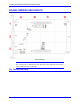
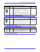
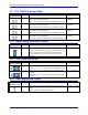
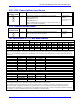
Table Of Contents
3U Turbo CPU Board for UMAC Turbo and Turbo Stack
Turbo CPU Board Jumpers and Pinouts 15
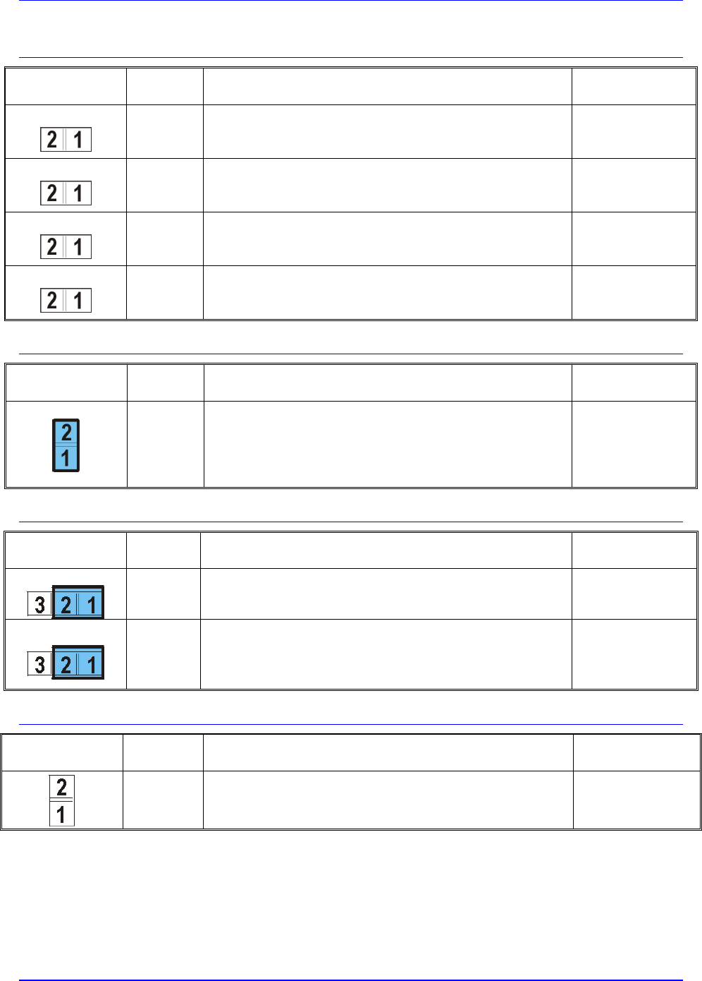
E7 – E10: IRQ PC Interrupt Select
E Point and
Physical Layout
Location Description Default
E7:
C-1 Jump E7 pin 1 to 2 to permit UMAC to interrupt PC on
PC/104 bus interrupt line IRQ10.
Remove E7 jumper to inhibit interrupt capability on this line.
No jumper
installed
E8:
C-1 Jump E8 pin 1 to 2 to permit UMAC to interrupt PC on
PC/104 bus interrupt line IRQ11.
Remove E8 jumper to inhibit interrupt capability on this line.
No jumper
installed
E9:
C-1 Jump E9 pin 1 to 2 to permit UMAC to interrupt PC on
PC/104 bus interrupt line IRQ12.
Remove E9 jumper to inhibit interrupt capability on this line.
No jumper
installed
E10:
C-1 Jump E10 pin 1 to 2 to permit UMAC to interrupt PC on
PC/104 bus interrupt line IRQ15.
Remove E10 jumper to inhibit interrupt capability on this line.
No jumper
installed
E12: Digital/Analog Reference Connect
E Point and
Physical Layout
Location Description Default
B-2 Jump pin 1 to 2 to tie digital GND reference to analog AGND
reference when using joint supply (e.g. from TB1 or PC/104).
Remove jumper to maintain separate GND and AGND
reference voltages to keep isolation when using separate
supplies.
Pins 1-2 jumpered
E17 – E18: Serial Port Select
E Point and
Physical Layout
Location Description Default
E17:
A-3 Jump E17 pin 1 to 2 to select RS-232 serial data input from J7.
Jump E17 pin 2 to 3 to select RS-422 serial data input from J8.
Pins 1-2 jumpered
E18:
A-3 Jump E18 pin 1 to 2 to select RS-232 serial handshake input
from J7.
Jump E18 pin 2 to 3 to select RS-422 serial handshake input
from J8.
Pins 1-2 jumpered
E19: Watchdog Disable Jumper
E Point and
Physical Layout
Location Description Default
A-1 Jump pin 1 to 2 to disable Watchdog timer (for test purposes
only).
Remove jumper to enable Watchdog timer.
No jumper installed