^1 HARDWARE REFERENCE MANUAL ^2 3U Turbo CPU Board (3U Turbo PMAC2) ^3 HRM for UMAC Turbo & Turbo Stack ^4 3xx-603382-xHxx ^5 June 8, 2004 Single Source Machine Control Power // Flexibility // Ease of Use 21314 Lassen Street Chatsworth, CA 91311 // Tel. (818) 998-2095 Fax. (818) 998-7807 // www.deltatau.
Copyright Information © 2003 Delta Tau Data Systems, Inc. All rights reserved. This document is furnished for the customers of Delta Tau Data Systems, Inc. Other uses are unauthorized without written permission of Delta Tau Data Systems, Inc. Information contained in this manual may be updated from time-to-time due to product improvements, etc., and may not conform in every respect to former issues. To report errors or inconsistencies, call or email: Delta Tau Data Systems, Inc.
U Turbo CPU Board for UMAC Turbo & Turbo Stack Table of Contents INTRODUCTION .......................................................................................................................................................1 UMAC CPU Boards ......................................................................................................................................................1 Associated Manuals.............................................................................................
3U Turbo CPU Board for UMAC Turbo and Turbo Stack J8: Auxiliary Serial Port Connector (RS232) .............................................................................................................20 TB1: 4-Pin Terminal Block .........................................................................................................................................20 ACCESSORIES ...............................................................................................................................
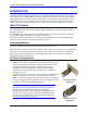
3U Turbo CPU Board for UMAC Turbo and Turbo Stack INTRODUCTION Delta Tau’s 3U-format Turbo PMAC systems combine the power of the Turbo PMAC family with an integrated packaging strategy that gives the user revolutionary flexibility and ease of use. The heart of these systems is the 3U Turbo PMAC CPU board, described in this manual.
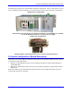
3U Turbo CPU Board for UMAC Turbo and Turbo Stack The following two photos show typical UMAC and Stack configurations. They are intended only to show what a completed system may look like, not to be instructions on how to put a particular system together.
3U Turbo CPU Board for UMAC Turbo and Turbo Stack UMAC and 3U-Stack Products UMAC Products Stack Products UMAC Turbo UMAC MACRO Turbo Stack MACRO Stack The UMAC Turbo is composed of a 3U-format Turbo PMAC2 CPU board and a set of accessory boards in 3U-format, all plugged in a common UBUS backplane and installed inside a 3U format rack.
3U Turbo CPU Board for UMAC Turbo and Turbo Stack 4 Introduction
3U Turbo CPU Board for UMAC Turbo and Turbo Stack BOARD CONFIGURATION The base version of the 3U Turbo PMAC2 CPU board provides a 1-slot 3U-format Eurocard board with: • 80 MHz DSP56303 CPU (120 MHz PMAC equivalent) • 128k x 24 SRAM compiled/assembled program memory (Opt. 5C0) • 128k x 24 SRAM user data memory (Opt. 5C0) • 1M x 8 flash memory for user backup & firmware (Opt.
3U Turbo CPU Board for UMAC Turbo and Turbo Stack The flash memory IC is located in U10. This IC forms the non-volatile memory for the board’s firmware, the user setup variables, and for user programs, tables, and buffers. It can be 1M x 8, 2M x 8, or 4M x 8 in capacity. • Option 5C0 is the standard CPU and memory configuration. It is provided automatically if no Option 5xx is specified.
3U Turbo CPU Board for UMAC Turbo and Turbo Stack • • Option 16A provides a 32k x 24 bank of battery-backed parameter RAM in components U17, U18, and U19, fitting in the smaller footprint for those locations. Option 16B provides a 128k x 24 bank of battery-backed parameter RAM in components U17, U18, and U19, filling the full footprint for those locations.
3U Turbo CPU Board for UMAC Turbo and Turbo Stack 8 Board Configuration
3U Turbo CPU Board for UMAC Turbo and Turbo Stack HARDWARE SETUP Clock Source Jumpers In order to operate, the Turbo CPU board must receive servo and phase clock signals from a source external to the board. These clock signals can be brought into the board from one of three possible ports: the stack connector, the UBUS backplane connector, or the front-side main serial-port connector. Jumpers E1A and E1B must be configured properly for the clock source used.
3U Turbo CPU Board for UMAC Turbo and Turbo Stack Reference Voltage Connect Jumper Jumper E12 permits the reference voltage for the analog and digital circuits in the 3U Turbo PMAC2 system to be tied together. If you are not isolating the analog circuits from the digital circuits, this jumper should be ON. (Note that in a Turbo Stack system, you cannot isolate these circuits from each other.
3U Turbo CPU Board for UMAC Turbo and Turbo Stack CONNECTIONS Stack Connections If the 3U Turbo CPU board is used in a Turbo Stack configuration, the stack accessory boards (Acc-2E, 3E, 4E, and 6E) are mounted on top (component side) of the CPU board. The solder-side prong connectors of these stack boards insert into the mating component-side sockets of the board below it. All four corners of these boards provide mounting holes for standoff connections between boards.
3U Turbo CPU Board for UMAC Turbo and Turbo Stack 12 Connections
3U Turbo CPU Board for UMAC Turbo and Turbo Stack BOARD JUMPERS AND PINOUTS The Location columns of the following tables refer to the mapped locations shown in the drawing below: CPU Card Layout Note: Pin 1 of an E-point is masked by an X in white ink on the composite side, and by a square solder pad on the solder side.
3U Turbo CPU Board for UMAC Turbo and Turbo Stack E1A: Servo and Phase Clock Direction Control E Point and Physical Layout Location Description Default A-2 Jump pins 1 and 2 or remove jumper for the UMAC Turbo system to use its internally generated servo and phase clock signals and to output these signals on the J7 serial port connector on the Turbo CPU board. Use E1B to connect pins 2 and 3 or remove it.
3U Turbo CPU Board for UMAC Turbo and Turbo Stack E7 – E10: IRQ PC Interrupt Select E Point and Physical Layout Location Description E7: C-1 E8: C-1 E9: C-1 E10: C-1 Jump E7 pin 1 to 2 to permit UMAC to interrupt PC on PC/104 bus interrupt line IRQ10. Remove E7 jumper to inhibit interrupt capability on this line. Jump E8 pin 1 to 2 to permit UMAC to interrupt PC on PC/104 bus interrupt line IRQ11. Remove E8 jumper to inhibit interrupt capability on this line.
3U Turbo CPU Board for UMAC Turbo and Turbo Stack E20 – E22: Power-Up/Reset Load Source E Point and Physical Layout Location Description Default E20: C-3 To load active memory from flash IC on power-up/reset, Remove jumper E20; Jump E21 pin 1 to 2. Jump E22 pin 1 to 2. Other combinations are for factory use only; the board will not operate in any other configuration.
3U Turbo CPU Board for UMAC Turbo and Turbo Stack BOARD CONNECTOR SUMMARY Stack Connector J1: Stack Connector J2: PC/104 Main Connector, 64-pin prong connector (Option 2 required) J1A, B: PC/104 AT Connector, 40-pin prong connector (Option 2 required) J2C, D: JTAG/OnCE (for factory use only): 10-pin IDC connector J5: JISP (for factory use only): 8-pin SIP connector J6: RS-232/RS-422 Serial Port Connector J7: * Auxiliary RS-232 Serial Port (Option 9T required) J8: * JISP_B (for factory use only) (SIP 8 conn
Turbo CPU Board for UMAC Turbo & Turbo Stack 18 Turbo PMAC2 3U CPU Board Connector Summary
3U Turbo CPU Board for UMAC Turbo and Turbo Stack BOARD CONNECTOR PINOUTS J7: RS-232/422 Serial Port Connector (26-pin Header at Location A-2) Front View Pin # Symbol Function Description Notes 1 CHASSI Common Turbo PMAC2-3U Common 2 S+5V Output +5VDC Supply Deactivated by ES 3 RD- / RXDInput Receive Data Diff. low TRUE / low TRUE 4 RD+ Input Receive Data Diff. high TRUE 5 SD- / TXDOutput Send Data Diff. low TRUE / low TRUE 6 SD+ Output Send Data Diff. high TRUE 7 CS+ / CTS Input Clear to Send Diff.
Turbo CPU Board for UMAC Turbo & Turbo Stack J8: Auxiliary Serial Port Connector (RS232) (10-pin Header at Location A-3) Pin # Symbol Function Front View Description Notes 1 PHASE In/Out Phasing Clock 2 DTR Bidirect Data Terminal Ready Shorted to DSR. 3 TXD/ Input Receive Data Low TRUE 4 CTS Input Clear to Send High TRUE 5 RXD/ Output Send Data Low TRUE 6 RTS Output Request to Send High TRUE 7 DSR Bidirect Data Set Ready Shorted to DTR.
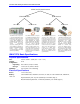
Acc-24E2, 2-Axis Digital PWM, 300603397-10x Acc-24E2A Option 1A, Additional 2Axis Analog, 3A1-603398-10x Acc-3E1, 48/96/144 I/O, 300-60335910x Acc-11E, Isolated 24-In/24-Out Board, 300-603307-10x Acc-15E, 12 In / 12 Out, Opto22, 300603488-10x UMAC Backplane-Mountable Accessory Boards – Axis Accessories UMAC Backplane-Mountable Accessory Boards – I/O Stack Piggyback Accessory Boards Option 2 Family: Bus Interface (Stack Configuration Only) Option 8 Family: High-Accuracy Clock Crystal Option 18 Family: I
22 UMAC Chassis Assemblies (Rack) Power Supplies – AC Input Power Supplies – DC Input Amplifiers – Digital PWM Input (brushless) Amplifiers – Analog ±10VDC Input (Brush Motors) UBUS (UMAC’s Backplane Boards) UMAC Backplane-Mountable Accessory Boards – Communication UMAC Backplane-Mountable Accessory Boards – Miscellaneous Acc-F, 3U DC to DC Converter, 10A, 30F-603216-OPT Acc-E, 3U AC Power Supply, 8A, 30E-603269-OPT 3U Rack, 10-1/2 Slot (42T) 542602932-10x 3U Rack, Variable Width per Customer Requir