
User's Manual


Turbo PMAC User Manual
Synchronizing Turbo PMAC to External Events 363
3. Compare output invert control bit: If this bit is set to 0, the off state is a low voltage out of the Servo
IC, and the on state is a high voltage. (Depending on the output driver circuitry, the actual output
from the card may be inverted from this.) If this bit is set to 1, the off state is a high voltage and the
on state is a low voltage. Note that this control bit can be used by itself to make the compare output a
general-purpose digital output, or in some cases, a software-driven interrupt to the host computer.
The single status bit is the position-compare flag, which shows the present state of the compare output
logic (and if the output is enabled, of the physical output). It is set to 1 if the compare output logic
state is on, and to a 0 if the output logic state is off.
There are no firmware functions for the automatic use of the position-compare circuitry. Your application
software must deal with the compare registers and control/status bits directly. Usually, these are accessed
with M-variables, and the file of suggested M-variables includes these definitions. For the first channel of
a Turbo PMAC (Servo IC 0 Channel 1), these definitions are:
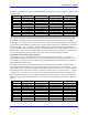
M101->X:$078001,0,24,S ; 24-bit position counter register
M103->X:$078003,0,24,S ; 24-bit position compare register
M111->X:$078000,11,1 ; Compare flag latch control
M112->X:$078000,12,1 ; Compare output enable control
M113->X:$078000,13,1 ; Compare output invert control
M116->X:$078000,16,1 ; Compare logic status
To preload a compare position, simply write a value to the compare register (e.g. M103=1250).
Example: We have an array of 50 points in P1 through P50 that represent the distances from a starting
position at which we want compare outputs. Program code (running just a single time) that could start
this process is:
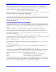
P100=1 ; Select first point of array
P101=M101 ; Read and store starting position
M103=P101+P(P100) ; Write first relative position to compare
M111=1 ; Set for latched output
M112=1 ; Enable compare output
Repeatedly executing program code (probably in a PLC 0 or PLCC 0) that could work through the array
is:
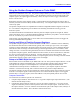
WHILE (P100<51) ; Loop until 50 points completed
IF (M116=1) ; Reached last compare position?
P100=P100+1 ; Select next point
M103=P101+P(P100) ; Write next relative position to compare
M111=0 ; Clear output by making transparent
M111=1 ; Set for latched output again
ENDIF
ENDWHILE
Setup on a PMAC2-Style Servo IC
Each encoder counter in PMAC2-style Servo IC has a position-compare function. Furthermore, the first
encoder counter (Channel 1) in each Servo IC can use the position-compare circuitry from any of the
other channels on the ASIC, so it can utilize up to four independent compare circuits.
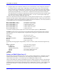
On the Turbo PMAC2-PC and the Turbo PMAC2-PCI, the compare outputs for Channel 1 and Channel 5
(if present) also can be used to interrupt the host computer over the backplane bus. Note that if the dual-
ported RAM ASCII communications interrupt function is enabled (I56=1 and I58=1), the compare output
for the board’s Channel 1 is used for this interrupt, and so cannot be used for true position compare
functions.