
User's Manual

Turbo PMAC User Manual
Setting Up Turbo PMAC-Based Commutation and/or Current Loop 121
Using the Test Results
To execute a power-on phasing using the hall-effect sensors, you can use new modes of the Ixx81 power-
on phase position parameter, or write a simple PLC program that executes once on power-up/reset.
Setting bit 23 of Ixx81 to 1 specifies a hall-effect power-on phase reference. In this case, the address
portion of Ixx81 specifies a Turbo PMAC X-address, usually that of the flag register used for the motor,
the same address as in Ixx25.
Turbo PMAC expects to find the hall-effect inputs at bits 20, 21, and 22 of the specified register. In a flag
register, these bits match the CHWn, CHVn, and CHUn inputs, respectively. Hall-effect inputs are
traditionally labeled U, V, and W.
Each hall-effect signal must have a duty cycle of 50% (180
o
e). PMAC can use hall-effect commutation
sensors separated by 120
o
e. There is no industry standard with hall-effect sensors as to direction sense or
zero reference, so this must be handled with software settings of Ixx81.
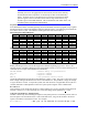
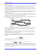
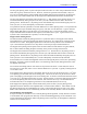
Bit 22 controls the direction sense of the hall-effect sensors as shown in the following diagrams, where a
value of 0 for bit 22 is standard and a value of 1 is reversed:
U
V
W
-30 30 90 150 -150 -90
1
0
1
0
1
0
30 -30 -90 -150 90150
Standard:
Reversed:
UVW Value: 132645
This diagram shows the hall-effect waveforms with zero offset, defined such that the V-signal transition
when the U-signal is low (defined as the zero point in the hall-effect cycle) represents the zero point in
PMAC’s commutation cycle.
If the hall-effect sensors do not have this orientation, bits 16 to 21 of Ixx81 can be used to specify the
offset between PMAC’s zero point and the hall-effect zero point. These bits can take a value of 0 to 63
with units of 1/64 of a commutation cycle (5.625
o
e).
The offset can be computed using the mapping test shown above. In our example, the hall effect zero
(HEZ) point was found to be between 30
o
e and 90
o
e, so we will call 60
o
e. The offset value can be
computed as
64*
o
o
360
360%HEZ
Offset =
The offset computed here should be rounded to the nearest integer.
In our example, this comes to:
hex011667.1064
o
360
o
60
64
o
o
360
360%
o
60
Offset
Β
=≈=∗=∗=
The test showed that the hall-effect sensors were in the standard direction, not reversed, so bit 22 is left at
zero. With bit 23 (a value of 8 in the first hex digit) set to 1 to specify hall effect sensing, the first two
hex digits of Ixx81 become $B5. If Flag register 1 at address $C000 were used for the hall-effect inputs,
Ixx81 would be set to $B5C000.