
User's Manual

Turbo PMAC User Manual
Setting Up Turbo PMAC-Based Commutation and/or Current Loop 113
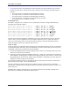
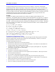
Sine-Wave Mode Command Output Addresses –
PMAC-style Servo ICs (Y-registers)
IC# - Chan# 0 – 1&2 0 – 3&4 1 – 1&2 1 – 3&4
Ixx02
$078002 $07800A $078102 $07810A
IC# - Chan# 2 - 1&2 2 - 3&4 3 - 1&2 3 - 3&4
Ixx02
$078202 $07820A $078302 $07830A
IC# - Chan# 4 - 1&2 4 - 3&4 5 - 1&2 5 - 3&4
Ixx02
$079202 $07920A $079302 $07930A
IC# - Chan# 6 - 1&2 6 - 3&4 7 - 1&2 7 - 3&4
Ixx02
$07A202 $07A20A $07A302 $07A30A
IC# - Chan# 8 - 1&2 8 - 3&4 9 - 1&2 9 - 3&4
Ixx02
$07B202 $07B20A $07B302 $07B309
Servo ICs 0 and 1 are on the Turbo PMAC itself.
Servo ICs 2 – 9 are on Acc-24P/V or Acc-51P boards.
Channels 1 – 4 on odd-numbered Servo ICs are Channels 5 – 8 on the boards.
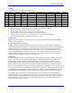
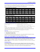
When using PMAC2-style Servo ICs for sine-wave control, Ixx02 must specify the address of the A DAC
register for a channel. In this mode, this will cause the Turbo PMAC to use both the A and the B DACs
for the channel. The following table shows the possible Ixx02 values for this mode:
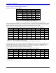
Sine-Wave Mode Command Output Addresses – PMAC2-style Servo ICs (Y-registers)
IC# - Chan# 0 - 1 0 - 2 0 - 3 0 - 4 1 - 1 1 - 2 1 - 3 1 - 4
Ixx02
$078002 $07800A $078012 $07801A $078102 $07810A $078112 $07811A
IC# - Chan# 2 - 1 2 - 2 2 - 3 2 - 4 3 - 1 3 - 2 3 - 3 3 - 4
Ixx02
$078202 $07820A $078212 $07821A $078302 $07830A $078312 $07831A
IC# - Chan# 4 - 1 4 - 2 4 - 3 4 - 4 5 - 1 5 - 2 5 - 3 5 - 4
Ixx02
$079202 $07920A $079212 $07921A $079302 $07930A $079312 $07931A
IC# - Chan# 6 - 1 6 - 2 6 - 3 6 - 4 7 - 1 7 - 2 7 - 3 7 - 4
Ixx02
$07A202 $07A20A $07A212 $07A21A $07A302 $07A30A $07A312 $07A31A
IC# - Chan# 8 - 1 8 - 2 8 - 3 8 - 4 9 - 1 9 - 2 9 - 3 9 - 4
Ixx02
$07B202 $07B20A $07B212 $07B21A $07B302 $07B30A $07B312 $07B31A
Servo ICs 0 and 1 are on the Turbo PMAC2 itself or on Acc-2E 3U-format stack boards.
Servo ICs 2 – 9 are on Acc-24x2 or Acc-51E boards.
Channels 1 – 4 on odd-numbered Servo ICs are Channels 5 – 8 on dual-Servo-IC boards.
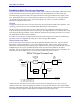
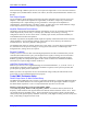
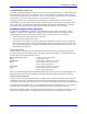
When performing sine-wave output control over the MACRO ring, Ixx02 must specify the address of the
MACRO node register for the A DAC causing the A and B DACs to be used. For the MACRO Type 1
protocol used by the Delta Tau MACRO Station, this is the address of Register 0 of the node. The
following table shows the possible Ixx02 values for this mode:
Sine-Wave Mode Command Output Addresses – MACRO ICs (Y-registers)
IC# - Node# 0 - 0 0 - 1 0 - 4 0 - 5 0 - 8 0 - 9 0 - 12 0 - 13
Ixx02
$078420 $078424 $078428 $07842C $078430 $078434 $078438 $07843C
IC# - Node# 1 - 0 1 - 1 1 - 4 1 - 5 1 - 8 1 - 9 1 - 12 1 - 13
Ixx02
$079420 $079424 $079428 $07942C $079430 $079434 $079438 $07943C
IC# - Node# 2 - 0 2 - 1 2 - 4 2 - 5 2 - 8 2 - 9 2 - 12 2 - 13
Ixx02
$07A420 $07A424 $07A428 $07A42C $07A430 $07A434 $07A438 $07A43C
IC# - Node# 3 - 0 3 - 1 3 - 4 3 - 5 3 - 8 3 - 9 3 - 12 3 - 13
Ixx02
$07B420 $07B424 $07B428 $07B42C $07B430 $07B434 $07B438 $07B43C
If using the older Type 0 MACRO protocol, add 1 to the value shown in the above table (e.g. $078420
becomes $078421).