
User's Manual

Turbo PMAC2 PCI Hardware Reference Manual
Baseboard Connector Pinouts 35
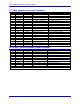
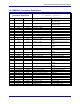
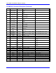
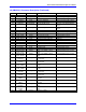
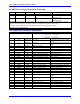
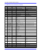
J11 (JMACH3) Connector Description (Continued)
Pin # Symbol Function Description Notes
23 ADC_CLK5+ Output A/D converter clock Programmable frequency
24 ADC_CLK5- Output A/D converter clock Programmable frequency
25 ADC_STB5+ Output A/D converter strobe Programmable sequence
26 ADC_STB5- Output A/D converter strobe Programmable sequence
27 ADC_DAA5+ Input Channel A ADC serial data MSB first
28 ADC_DAA5- Input Channel A ADC serial data MSB first
29 ADC_DAB5+ Input Channel B ADC serial data MSB first
30 ADC_DAB5- Input Channel B ADC serial data MSB first
31 AENA5+ Output Amplifier enable High is enable
32 AENA5- Output Amplifier enable Low is enable
33 FAULT5+ Input Amplifier fault Programmable parity
34 FAULT5- Input Amplifier fault Programmable parity
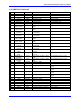
35 PWMATOP5+
DAC_CLK5+
Output Phase A top CMD or DAC
clock
Programmable function control
36 PWMATOP5-
DAC_CLK5-
Output Phase A top CMD or DAC
clock
Programmable function control
37 PWMABOT5+
DAC5A+
Output Phase A bottom CMD or DAC
A serial data
Programmable function control
38 PWMABOT5-
DAC5A-
Output Phase A bottom CMD or DAC
A serial data
Programmable function control
39 PWMBTOP5+
DAC_STB5+
Output Phase B top CMD or DAC
strobe
Programmable function control
40 PWMBTOP5-
DAC_STB5-
Output Phase B top CMD or DAC
strobe
Programmable function control
41 PWMBBOT5+
DAC5B+
Output Phase B bottom CMD or DAC
B serial data
Programmable function control
42 PWMBBOT5-
DAC5B-
Output Phase B bottom CMD or DAC
B serial data
Programmable function control
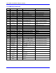
43 PWMCTOP5+
DIR5+
Output Phase B top CMD or PFM
direction
Programmable function control
44 PWMCTOP5-
DIR5-
Output Phase B top CMD. or PFM
direction
Programmable function control
45 PWMCBOT5+
PULSE5+
Output Phase B bottom CMD or PFM
pulse
Programmable function control
46 PWMCBOT5-
PULSE5-
Output Phase B bottom CMD or PFM
pulse
Programmable function control
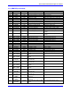
47 GND Common Reference voltage
48 GND Common Reference voltage
49 +5V Output/Input +5V power For external circuit or from external
supply
50 +5V Output/Input +5V power For external circuit or from external
supply
51 +5V Output/Input +5V power For external circuit or from external
supply
52 +5V Output/Input +5V power For external circuit or from external
supply
53 GND Common Reference voltage
54 GND Common Reference voltage
55 CHA6+ Input Encoder 6 positive A Channel Also pulse input
56 CHA6- Input Encoder 6 negative A Channel Also pulse input
57 CHB6+ Input Encoder 6 positive B Channel Also direction input