
User's Manual


Turbo PMAC2 PCI Hardware Reference Manual
Baseboard Connector Pinouts 25
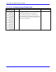
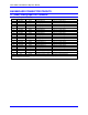
J3 (JI/O) General Input/Output Connector (Continued)
Pin # Symbol Function Description Notes
20 I/O19 In/Out Digital I/O 19 Software direction control
21 I/O20 In/Out Digital I/O 20 Software direction control
22 I/O21 In/Out Digital I/O 21 Software direction control
23 I/O22 In/Out Digital I/O 22 Software direction control
24 I/O23 In/Out Digital I/O 23 Software direction control
25 I/O24 In/Out Digital I/O 24 Software direction control
26 I/O25 In/Out Digital I/O 25 Software direction control
27 I/O26 In/Out Digital I/O 26 Software direction control
28 I/O27 In/Out Digital I/O 27 Software direction control
29 I/O28 In/Out Digital I/O 28 Software direction control
30 I/O29 In/Out Digital I/O 29 Software direction control
31 I/O30 In/Out Digital I/O 30 Software direction control
32 I/O31 In/Out Digital I/O 31 Software direction control
33 GND Common Reference voltage
34 GND Common Reference voltage
35 Phase/ Output Phase clock For latching data
36 Servo/ Output Servo clock For latching data
37 GND Common Reference voltage
38 GND Common Reference voltage To power external circuitry
39 +5V Output Supply voltage To power external circuitry
40 +5V Output Supply voltage
The JI/O connector provides 32 input/output pins at TTL levels. Direction can be controlled in byte-wide
groups.
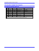
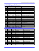
J5 (JRS232) Serial Port Connector
Pin # Symbol Function Description Notes
1 PHASE Output Phasing clock
2 DTR Bidirectional Data terminal ready Tied to DSR
3 TXD/ Input Receive data Host transmit data
4 DTS Input Clear to send Host ready bit
5 RXD/ Output Send data Host receive data
6 RTS Output Request to send PMAC ready bit
7 DSR Bidirectional Data set ready Tied to DTR
8 SERVO Output Servo clock
9 GND Common PMAC common
10 +5V Output +5Vdc supply Power supply out
The JRS232 connector provides the PMAC2-PC with the ability to communicate serially with an RS232 port.
This connector cannot be used for daisy chain interconnection of multiple PMACs. The J5A RS-422 port must
be used for daisy chaining. E17 and E18 must connect pins 1 and 2 to use the RS-232 port for serial
communications.