
User's Manual


Turbo PMAC2 PCI Hardware Reference Manual
Baseboard Jumper Descriptions 15
BASE BOARD JUMPER DESCRIPTIONS
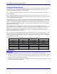
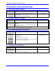
E1: Servo and Phase Clock Direction Control
E Point and
Physical Layout
Location Description Default
E1
C2 Remove jumper for PMAC2 PCI to use its internally
generated servo and phase clock signals and to output
these signals on the J5A serial port connector.
Jump pins 1 and 2 for PMAC2 PCI to expect to receive
its servo and phase clock signals on the J5A serial port
connector.
No jumper installed
Note: If the E1 jumper is ON and the servo and phase clocks are not brought in on the J5A serial port, the watchdog
timer will trip immediately.
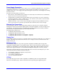
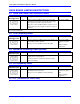
E2: CPU Frequency Select
E Point and
Physical Layout
Location Description Default
E2
C2 Remove jumper for 40 MHz operation (E4 OFF also) or
for 80 MHz operation (E4 ON).
Jump pin 1 to 2 for 60 MHz operation (E4 OFF).
No jumper installed
(standard or Option
5C)
Jumper installed
(Option 5B)
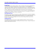
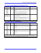
E3: Normal/Re-Initializing Power-Up/Reset
E Point and
Physical Layout
Location Description Default
E3
C2 Jump pin 1 to 2 to re-initialize on power-up/reset,
loading factory default settings.
Remove jumper for normal power up/reset, loading
user-saved settings.
No jumper installed
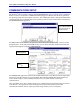
E4: CPU Frequency Select
E Point and
Physical Layout
Location Description Default
E4
C2 Remove jumper for 40MHz operation (E2 OFF also) or
for 60MHz operation (E4 ON).
Jump pin 1 to 2 for 80MHz operation (E2 OFF).
No jumper installed
(standard or Option
5B)
Jumper installed
(Option 5C)
E5 – E6: (Reserved for Future Use)