
User's Manual


Turbo PMAC2 PCI Hardware Reference Manual
16 Baseboard Jumper Descriptions
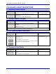
E13 - E14: Encoder Sample Clock Direction Control
E Point and
Physical Layout
Location Description Default
E13
D1 Remove jumper to output SCLK generated in first ASIC
on SCLK_12 and SCLK_34, or to control direction by
software.
Jump pins 1 to 2 to input SCLK signal for first ASIC on
SCLK_34 and output this signal on SCLK_12.
Jump pins 2 to 3 to input SCLK signal for first ASIC on
SCLK_12 and output this signal on SCLK_34.
No jumper installed
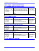
E14
D2 Remove jumper to output SCLK generated in second
ASIC on SCLK_56 and SCLK_78, or to control
direction by software.
Jump pins 1 to 2 to input SCLK signal for second ASIC
on SCLK_78 and output this signal on SCLK_56.
Jump pins 2 to 3 to input SCLK signal for second ASIC
on SCLK_56 and output this signal on SCLK_78
No jumper installed
Note: E14 is installed only if Option 1 has been ordered.
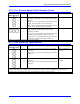
E17 - E18: Serial Port Type Selection
E Point and
Physical Layout
Location Description Default
E17
C1 Connect pins 1 and 2 to use the RS-232 port on the J5
connector.
Connect pins 2 and 3 to use the RS-422 port on the J5A
connector.
Jumper installed in 1-2
position.
E18
C1
Connect pins 1 and 2 to use the RS-232 port on the J5
connector.
Connect pins 2 and 3 to use the RS-422 port on the J5A
connector.
Jumper installed in 1-2
position.
Serial Port Choice: Because both RS-232 and RS-422 ports are always provided, jumpers must be set correctly to
use the port of your choice. Jumpers E17 and E18 must connect pins 1 and 2 to use the RS- 232 port on the J5
connector; they must connect pins 2 and 3 to use the RS-422 port on the J5A connector.