^1 HARDWARE REFERENCE MANUAL ^2 Turbo PMAC2 PCI ^3 Programmable Multi-Axis Controller ^4 4xx-603367-xHxx ^5 May 26, 2004 Single Source Machine Control Power // Flexibility // Ease of Use 21314 Lassen Street Chatsworth, CA 91311 // Tel. (818) 998-2095 Fax. (818) 998-7807 // www.deltatau.
Copyright Information © 2003 Delta Tau Data Systems, Inc. All rights reserved. This document is furnished for the customers of Delta Tau Data Systems, Inc. Other uses are unauthorized without written permission of Delta Tau Data Systems, Inc. Information contained in this manual may be updated from time-to-time due to product improvements, etc., and may not conform in every respect to former issues. To report errors or inconsistencies, call or email: Delta Tau Data Systems, Inc.
Turbo PMAC2 PCI Hardware Reference Manual Table of Contents INTRODUCTION .......................................................................................................................................................1 Board Configuration .................................................................................................................................................1 Base Version .........................................................................................................
Turbo PMAC2 PCI Hardware Reference Manual E17 - E18: Serial Port Type Selection ...................................................................................................................16 E111-118: Command Output Disable State...........................................................................................................17 MATING CONNECTORS .......................................................................................................................................
Turbo PMAC2 PCI Hardware Reference Manual INTRODUCTION The Turbo PMAC2 PCI (part number 400-603367-TRx) is a member of the Turbo PMAC family of boards optimized for interface to sinewave or direct-PWM servo drives and to pulse-and-direction stepper drives. Its software is capable of 32 axes of control. It can have up to eight channels of on-board axis interface circuitry.
Turbo PMAC2 PCI Hardware Reference Manual Option 5: CPU and Memory Configurations The various versions of Option 5 provide different CPU speeds and main memory sizes on the piggyback CPU board. Only one Option 5xx may be selected for the board. The CPU is a DSP5630x IC as component U1. It is currently available only as an 80 MHz device (with computational power equivalent to a 120 MHz non-Turbo PMAC), but higher speed versions will be available shortly.
Turbo PMAC2 PCI Hardware Reference Manual Option 8: High-Accuracy Clock Crystal The Turbo PMAC2 PCI has a clock crystal (component Y1) of nominal frequency 19.6608 MHz (~20 MHz). The standard crystal’s accuracy specification is +/-100 ppm. • Option 8A provides a nominal 19.6608 MHz crystal with a +/-15 ppm accuracy specification. Option 9: Serial Port Configuration The Turbo PMAC2 PCI comes standard with a single serial port that can use either RS-232 or RS-422 transceivers.
Turbo PMAC2 PCI Hardware Reference Manual 4 Introduction
Turbo PMAC2 PCI Hardware Reference Manual HARDWARE SETUP Piggyback Turbo CPU Board Jumper Configuration Watchdog Timer Jumper Jumper E1 on the Turbo CPU board must be OFF for the watchdog timer to operate. This is a very important safety feature, so it is vital that this jumper be OFF in normal operation. E1 should only be put ON to debug problems with the watchdog timer circuit.
Turbo PMAC2 PCI Hardware Reference Manual Re-Initialization Jumper If E3 is OFF during power-up/reset, the controller will load its last saved set-up parameters from flash memory into active memory. T his is the setting for normal operation. If E3 is ON during power-up/reset, the controller will load its factory-default set-up parameters from firmware into active memory. Generally this is only done if communications cannot be established with the card when in comes up in normal operational mode.
Turbo PMAC2 PCI Hardware Reference Manual Pull-Up/Pull-Down Resistors The differential input signal pairs to the PMAC2 PCI have user-configurable pull-up/pull-down resistor networks to permit the acceptance of either single-ended or differential signals in one setting, or the detection of lost differential signals in another setting. The ‘+’ inputs of each differential pair each have a hard-wired 1 kohm pull-up resistor to +5V. This cannot be changed.
Turbo PMAC2 PCI Hardware Reference Manual Power Supply Connection The standard PMAC2 PCI requires only 5V power: 3A in a 4-channel configuration, 4A in an 8-channel configuration (with Option 1). If the Option 12 A/D converters are installed, a –12V supply is also required. In this case, a +12V supply can be passed through the card and out to the analog devices feeding the A/D converters.
Turbo PMAC2 PCI Hardware Reference Manual Serial Ports The PMAC2 PCI has two serial-port connectors. Only one of these can be used in an application J5 is a 10-pin IDC header for RS-232 communications. It can be connected to a standard DB9 RS-232 connector on a host computer or terminal via a flat cable such as the Acc-3L. A commercially available DB9-to-DB25 adapter can be added to such a flat cable if the host computer or terminal has a DB25 serial connector.
Turbo PMAC2 PCI Hardware Reference Manual 10 Hardware Setup
Turbo PMAC2 PCI Hardware Reference Manual COMMUNICATIONS SETUP Delta Tau provides communication tools that take advantage of the PCI bus Plug and Play feature of 32bits Windows© based computers. Starting with MOTIONEXE.EXE version 10.32.00, which is included in Pewin 32 version 2.32 and newer, a PMAC2 PCI board plugged in a PCI bus slot will be recognized by the operating system when the computer is boot up.
Turbo PMAC2 PCI Hardware Reference Manual Note: For example, if a Device0 for serial RS-232 communications was defined before a PMAC PCI board was installed in the computer, its setup information will be overwritten by the MOTIONEXE application when the PMAC2 PCI board is found. Therefore, it is very important to take note of the all the devices and its parameters defined in MOTIONEXE before installing a new PMAC board in the computer.
Turbo PMAC2 PCI Hardware Reference Manual CPU BOARD E-POINT DESCRIPTIONS E1: Watchdog Disable Jumper E Point and Physical Layout E1 Description Jump pin 1 to 2 to disable Watchdog timer (for test purposes only). Remove jumper to enable Watchdog timer. Default No jumper installed E2: DPRAM Location Configure E Point and Physical Layout Description Default E2 Jump pin 1 to 2 to access the dual-ported RAM on Jumper connects pins 1 and baseboard.
Turbo PMAC2 PCI Hardware Reference Manual 14 CPU Board E-Point Descriptions
Turbo PMAC2 PCI Hardware Reference Manual BASE BOARD JUMPER DESCRIPTIONS E1: Servo and Phase Clock Direction Control E Point and Physical Layout Location E1 C2 Description Default Remove jumper for PMAC2 PCI to use its internally No jumper installed generated servo and phase clock signals and to output these signals on the J5A serial port connector. Jump pins 1 and 2 for PMAC2 PCI to expect to receive its servo and phase clock signals on the J5A serial port connector.
Turbo PMAC2 PCI Hardware Reference Manual E13 - E14: Encoder Sample Clock Direction Control E Point and Physical Layout Location E13 D1 Description Default Remove jumper to output SCLK generated in first ASIC on SCLK_12 and SCLK_34, or to control direction by software. Jump pins 1 to 2 to input SCLK signal for first ASIC on SCLK_34 and output this signal on SCLK_12. Jump pins 2 to 3 to input SCLK signal for first ASIC on SCLK_12 and output this signal on SCLK_34.
Turbo PMAC2 PCI Hardware Reference Manual E111-118: Command Output Disable State E Point and Physical Layout Location C1 Description Jump pin 1 to 2 of E11n for digital servo command output signals of Channel n to tri-state when amplifier enable signal for Channel n is in disable state. Default No jumper installed Remove jumper for digital servo command output signals of Channel n to remain active (but typically with zero command value) when amplifier enable signal for Channel n is in disable state.
Turbo PMAC2 PCI Hardware Reference Manual 18 Baseboard Jumper Descriptions
Turbo PMAC2 PCI Hardware Reference Manual MATING CONNECTORS CPU Board Connectors J2 (JEXP)/Expansion 1. Two 50-pin female flat cable connector Delta Tau P/N 014-R00F50-0K0 T&B Ansley P/N 609-5041 2. 171-50 T&B Ansley standard flat cable stranded 50-wire 3. Phoenix varioface module type FLKM 50 (male pins) P/N 22 81 08 9 J8 (JAUX232)/Auxiliary RS232 1. Two 10-pin female flat cable connector Delta Tau P/N 014-ROOF10-0K0 T&B Ansley P/N 609-1041 2. 171-10 T&B Ansley standard flat cable stranded 10-wire 3.
Turbo PMAC2 PCI Hardware Reference Manual J8 (JEQU)/Position Compare 1. Two 10-pin female flat cable connector Delta Tau P/N 014-ROOF10-0K0 T&B Ansley P/N 609-1041 2. 171-10 T&B Ansley standard flat cable stranded 10-wire 3. Phoenix varioface module type FLKM 10 (male pins) P/N 22 81 01 8 J9 (JMACH1)/Machine Port 1 1. Two 100-pin high-density box header with center key, 0.050” pitch, AMP P/N 1-04068-7, Delta Tau P/N 014-00010-FPB 2. High-density flat cable stranded 100-wire J10 (JMACH2)/Machine Port 2 1.
Turbo PMAC2 PCI Hardware Reference Manual CPU BOARD CONNECTOR PINOUTS J8 (JAUX232)/Auxiliary Serial Port Pin # Symbol Function Description Notes 1 No connect 2 DTR Bidirectional Data terminal ready Tied to DRR 3 TXD/ Input Receive data Host transmit data 4 CTS Input Clear to Send Host ready bit 5 RXD/ Output Send data Host receive data 6 RTS Output Request to Send PMAC ready bit 7 DSR Bidirectional Data set ready Tied to DTR 8 No connect 9 GND Common PMAC common 10 +5V Output 10 +5Vdc supply Power sup
Turbo PMAC2 PCI Hardware Reference Manual 22 CPU Board Connector Pinouts
Turbo PMAC2 PCI Hardware Reference Manual BASEBOARD CONNECTOR PINOUTS J1 (JANA) Analog Input Port Connector (Present only if Option 12 ordered) Pin # Symbol Function Description Notes 1 ANAI00 Input Analog Input 0 0-5V or +/-2.5V range 2 ANAI01 Input Analog Input 1 0-5V or +/-2.5V range 3 ANAI02 Input Analog Input 2 0-5V or +/-2.5V range 4 ANAI03 Input Analog Input 3 0-5V or +/-2.5V range 5 ANAI04 Input Analog Input 4 0-5V or +/-2.5V range 6 ANAI05 Input Analog Input 5 0-5V or +/-2.
Turbo PMAC2 PCI Hardware Reference Manual J2 (JTHW) Multiplexer Port Connector Pin # Symbol Function Description 1 2 3 4 5 6 7 8 9 10 11 12 13 14 15 16 17 18 19 20 21 22 23 24 25 26 GND GND DAT0 SEL0 DAT1 SEL1 DAT2 SEL2 DAT3 SEL3 DAT4 SEL4 DAT5 SEL5 DAT6 SEL6 DAT7 SEL7 NC GND BRLD/ GND IPLD/ GND +5V INIT/ Common Common Input Output Input Output Input Output Input Output Input Output Input Output Input Output Input Output NC Common Output Common Output Common Output Input PMAC common PMAC common Data
Turbo PMAC2 PCI Hardware Reference Manual J3 (JI/O) General Input/Output Connector (Continued) Pin # Symbol Function Description Notes 20 I/O19 In/Out Digital I/O 19 Software direction control 21 I/O20 In/Out Digital I/O 20 Software direction control 22 I/O21 In/Out Digital I/O 21 Software direction control 23 I/O22 In/Out Digital I/O 22 Software direction control 24 I/O23 In/Out Digital I/O 23 Software direction control 25 I/O24 In/Out Digital I/O 24 Software direction control 26 I/O25 In/Out Digital
Turbo PMAC2 PCI Hardware Reference Manual J5A: RS422 Serial Port Connector JRS422 (26-Pin Connector) Pin # Symbol Function Description Notes 1 CHASSI Common PMAC common 2 S+5V Output +5Vdc supply 3 RDInput Receive data Diff. I/O low true 4 RD+ Input Receive data Diff. I/O high true 5 SDOutput Send data Diff. I/O low true 6 SD+ Output Send data Diff. I/O high true 7 CS+ Input Clear to send Diff. I/ O high true 8 CSInput Clear to send Diff. I/O low true 9 RS+ Output Request to send Diff.
Turbo PMAC2 PCI Hardware Reference Manual J7 (JHW) Handwheel Encoder Connector Pin # Symbol Function Description 1 2 3 4 5 6 7 8 9 10 11 12 13 14 15 16 17 18 19 20 GND +5V HWAL+ HWALHWBL+ HWBLHWA2+ HWA2HWB2+ HWB2PUL1+ PUL1DIR1+ DIR1PUL2+ PUL2DIR2+ DIR2GND +5V Common Output Input Input Input Input Input Input Input Output Output Output Output Output Output Output Output Output Common Output Reference voltage Supply voltage HW positive A Channel HW negative A Channel HW negative B Channel HW negative
Turbo PMAC2 PCI Hardware Reference Manual J9 (JMACH1) Connector Description J9 (JMACH1) Connector Description Pin # Symbol Function Description Notes 1 +5V Output/Input +5V power 2 +5V Output/Input +5V power For external circuit or from external supply For external circuit or from external supply 3 4 5 6 7 8 9 10 11 GND GND CHA1+ CHA1CHB1+ CHB1CHC1+ CHC1CHU1 Common Common Input Input Input Input Input Input Input 12 CHV1 Input Channel 1 V flag 13 CHW1 Input Channel 1 W flag 14 15
Turbo PMAC2 PCI Hardware Reference Manual J9 (JMACH1) Connector Description (Continued) Pin # Symbol Function 35 Output 47 48 49 PWMATOP1+ DAC_CLK1+ PWMATOP1DAC_CLK1PWMABOT1+ DAC1A+ PWMABOT1DAC1APWMBTOP1+ DAC_STB1+ PWMBTOP1DAC_STB1PWMBBOT1+ DAC1B+ PWMBBOT1DAC1BPWMCTOP1+ DIR1+ PWMCTOP1DIR1PWMCBOT1+ PULSE1+ PWMCBOT1PULSE1GND GND +5V Description Notes Programmable function control Common Common Output/Input Phase A top CMD or DAC clock Phase A top CMD or DAC clock Phase A bottom CMD or DAC A serial
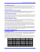
Turbo PMAC2 PCI Hardware Reference Manual J9 (JMACH1) Connector Description (Continued) Pin # Symbol Function Description Notes 66 67 68 69 70 71 PLIM2 MLIM2 HOME2 ACCFLT2 WD0/ SCLK12+ Input Input Input Input Output Input/Output Positive overtravel limit Negative overtravel limit Home switch input Accessory fault flag Watchdog output Encoder sample clock 72 SCLK12- Input/Output Encoder sample clock 73 74 75 76 77 78 79 80 81 82 83 84 85 ADC_CLK2+ ADC_CLK2ADC_STB2+ ADC_STB2ADC_DAA2+ ADC_DAA2AD
Turbo PMAC2 PCI Hardware Reference Manual J9 (JMACH1) Connector Description (Continued) Pin # Symbol Function 98 99 GND +5V Common Output/Input Description Notes Reference voltage +5V power For external circuit or from external supply 100 +5V Output/Input +5V power For external circuit or from external supply The JMACH1 connector provides the interface pins for channels 1 and 2.
Turbo PMAC2 PCI Hardware Reference Manual J10 (JMACH2) (Continued) Pin # Symbol Function 28 29 30 31 32 33 34 35 Input Input Input Output Output Input Input Output 47 48 49 ADC_DAA3ADC_DAB3+ ADC_DAB3AENA3+ AENA3FAULT3+ FAULT3PWMATOP3+ DAC_CLK3+ PWMATOP3DAC_CLK3PWMABOT3+ DAC3A+ PWMABOT3DAC3APWMBTOP3+ DAC_STB3+ PWMBTOP3DAC_STB3PWMBBOT3+ DAC3B+ PWMBBOT3DAC3BPWMCTOP3+ DIR3+ PWMCTOP3DIR3PWMCBOT3+ PULSE3+ PWMCBOT3PULSE3GND GND +5V Description Notes MSB first MSB first MSB first High is enable Low is enab
Turbo PMAC2 PCI Hardware Reference Manual J10 (JMACH2) (Continued) Pin # Symbol Function Description Notes 61 62 63 64 65 66 67 68 69 70 71 CHU4 CHV4 CHW4 CHT4 USER4 PLIM4 MLIM4 HOME4 ACCFLT4 WD0/ SCLK34+ Input Input Input Input Input Input Input Input Input Output Input/Output Channel 4 U flag Channel 4 V flag Channel 4 W flag Channel 4 T flag General purpose user flag Positive overtravel limit Negative overtravel limit Home switch input Accessory fault flag Watchdog output Encoder sample clock 7
Turbo PMAC2 PCI Hardware Reference Manual J10 (JMACH2) (Continued) Pin # Symbol Function 95 PWMCBOT4+ PULSE4+ PWMCBOT4PULSE4GND GND +5V Output 96 97 98 99 Output Common Common Output/Input Description Notes Phase B bottom CMD or PFM pulse Phase B bottom CMD or PFM pulse Reference voltage Reference voltage +5V power Programmable function control Programmable function control For external circuit or from external supply 100 +5V Output/Input +5V power For external circuit or from external supply T
Turbo PMAC2 PCI Hardware Reference Manual J11 (JMACH3) Connector Description (Continued) Pin # Symbol Function 23 24 25 26 27 28 29 30 31 32 33 34 35 Output Output Output Output Input Input Input Input Output Output Input Input Output 47 48 49 ADC_CLK5+ ADC_CLK5ADC_STB5+ ADC_STB5ADC_DAA5+ ADC_DAA5ADC_DAB5+ ADC_DAB5AENA5+ AENA5FAULT5+ FAULT5PWMATOP5+ DAC_CLK5+ PWMATOP5DAC_CLK5PWMABOT5+ DAC5A+ PWMABOT5DAC5APWMBTOP5+ DAC_STB5+ PWMBTOP5DAC_STB5PWMBBOT5+ DAC5B+ PWMBBOT5DAC5BPWMCTOP5+ DIR5+ PWMCTOP5DIR5PWM
Turbo PMAC2 PCI Hardware Reference Manual J11 (JMACH3) (Continued) Pin # Symbol Function Description Notes 58 59 60 61 62 63 64 65 66 67 68 69 70 71 CHB6CHC6+ CHC6CHU6 CHV6 CHW6 CHT6 USER6 PLIM6 MLIM6 HOME6 ACCFLT6 WD0/ SCLK56+ Input Input Input Input Input Input Input Input Input Input Input Input Output Input/Output Encoder 6 negative B Channel Encoder 6 positive C Channel Encoder 6 negative C Channel Channel 6 U flag Channel 6 V flag Channel 6 W flag Channel 6 T flag General purpose user flag Po
Turbo PMAC2 PCI Hardware Reference Manual J11 (JMACH3) (Continued) Pin # Symbol Function 96 PWMCBOT6PULSE6GND GND +5V Output 97 98 99 Common Common Output/Input Description Notes Phase B bottom CMD or PFM pulse Reference voltage Reference voltage +5V power Programmable function control For external circuit or from external supply 100 +5V Output/Input +5V power For external circuit or from external supply The JMACH1 connector provides the interface pins for channels 5 and 6.
Turbo PMAC2 PCI Hardware Reference Manual J12 (JMACH4) Connector Description (Continued) Pin # Symbol Function 28 29 30 31 32 33 34 35 Input Input Input Output Output Input Input Output 47 48 49 ADC_DAA7ADC_DAB7+ ADC_DAB7AENA7+ AENA7FAULT7+ FAULT7PWMATOP7+ DAC_CLK7+ PWMATOP7DAC_CLK7PWMABOT7+ DAC7A+ PWMABOT7DAC7APWMBTOP7+ DAC_STB7+ PWMBTOP7DAC_STB7PWMBBOT7+ DAC7B+ PWMBBOT7DAC7BPWMCTOP7+ DIR7+ PWMCTOP7DIR7PWMCBOT7+ PULSE7+ PWMCBOT7PULSE7GND GND +5V Description Notes MSB first MSB first MSB first High
Turbo PMAC2 PCI Hardware Reference Manual J12 (JMACH4) Connector Description (Continued) Pin # Description Notes 62 63 64 65 66 67 68 69 70 71 CHV8 CHW8 CHT8 USER8 PLIM8 MLIM8 HOME8 ACCFLT8 WD0/ SCLK78+ Input Input Input Input Input Input Input Input Output Input/Output Channel 8 V flag Channel 8 W flag Channel 8 T flag General purpose user flag Positive overtravel limit Negative overtravel limit Home switch input Accessory fault flag Watchdog output Encoder sample clock 72 SCLK78- Input/Output E
Turbo PMAC2 PCI Hardware Reference Manual J12 (JMACH4) Connector Description (Continued) Pin # Symbol Function 96 PWMCBOT8PULSE8GND GND +5V Output 97 98 99 Common Common Output/Input Description Notes Phase B bottom CMD or PFM pulse Reference voltage Reference voltage +5V power Programmable function control For external circuit or from external supply 100 +5V Output/Input +5V power For external circuit or from external supply The JMACH1 connector provides the interface pins for channels 3 and 4
Turbo PMAC2 PCI Hardware Reference Manual BASE BOARD JUMPERS LAYOUT Baseboard Jumpers Layout 41
Turbo PMAC2 PCI Hardware Reference Manual 42 Baseboard Jumpers Layout
Schematics SCHEMATICS Turbo PMAC2 PCI Hardware Reference Manual 43
44 Schematics Turbo PMAC2 PCI Hardware Reference Manual
Schematics Turbo PMAC2 PCI Hardware Reference Manual 45
46 Schematics Turbo PMAC2 PCI Hardware Reference Manual
Schematics Turbo PMAC2 PCI Hardware Reference Manual 47