
User's Manual

Turbo PMAC User Manual
Motor Compensation Tables and Constants 159
(
)
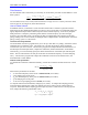
ivpvoldnew
KK*30Ixx30Ixx
+
=
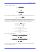
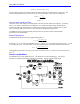
The zero and pole terms use the first-order notch filter parameters Ixx36 and Ixx38, respectively. The
second-order parameters Ixx37 and Ixx39 are set to zero if the filter is used only as an integrator.
ivpv
pv
KK
K
36Ixx
+
−=
138Ixx
−
=
Use to Create a Lead-Lag Filter
This filter can be used simply as a lead-lag filter if the roots are real rather than imaginary. A lead-lag
filter is very similar in performance to a PID filter. It is useful when filter settings are determined
analytically rather than experimentally. When a basic lead-lag servo filter is desired, all servo gains
Ixx31 to Ixx35 should be set to zero; Ixx30 is still used as the generalized gain term.
The PMAC Executive program presently does not have any screens to assist in the automatic
specification of a lead-lag filter.
Manual Specification
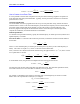
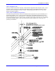
The generalized analytical form of a digital lead-lag filter is:
(
)
()
(
)
()
dz
cz
bz
az
K)z(L
+
+
+
+
=
where the (z+a)/(z+b) term is the lead filter, with a < b, the (z+c)/(z+d) term is the lag filter, with c > d, and
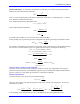
K is the DC gain term. In Turbo PMAC’s real-time implementation, the transfer function of the filter is:
2
z
2
d
1
bdz1
2
z
2
c
1
acz1
K)z(L
−
+
−
+
−
+
−
+
=
Turbo PMAC term Ixx30 is set to K; Ixx36 is set to ac; Ixx37 is set to c
2
; Ixx38 is set to bd; and Ixx39 is
set to d
2
.
Servo-Loop Modifiers
The PID filter has several modifying terms – non-linearities in control terminology – that can be
important to optimize the filter for performance and safety. Each is covered briefly below.