
User's Manual


PMAC VME Hardware Reference Manual
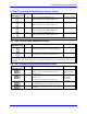
4 PMAC VME E-Point Descriptions
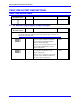
E17A-E17D: Amplifier-Enable/Direction Polarity Control
E Point and
Physical Layout
Location Description Default
E17A
B2 Jump 1-2 for high TRUE AENA (1-4).
Remove jumper for low TRUE AENA (1-4).
No jumper installed
E17B
C2 Jump 1-2 for high TRUE AENA (1-4).
Remove jumper for low TRUE AENA (1-4).
No jumper installed
E17C
C2 Jump 1-2 for high TRUE AENA (1-4).
Remove jumper for low TRUE AENA (1-4).
No jumper installed
E17D
C2 Jump 1-2 for high TRUE AENA (1-4).
Remove jumper for low TRUE AENA (1-4).
No jumper installed
Low-true enable is the fail-safe option because of the sinking (open-collector) ULN2803A output driver IC.
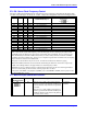
E22 - E23: Control Panel Handwheel Enable
E Point and
Physical Layout
Location Description Default
E22
C2 Jump pin 1 to 2 to obtain handwheel encoder signal
from front panel at J2-16 for CHB2 (ENC2-B).
No jumper
E23
C2 Jump pin 1 to 2 to obtain handwheel encoder signal
from front panel at J2-22 for CHA2 (ENC2-A).
No jumper
With these jumpers ON, no encoder should be wired into ENC2 on JMACH1. Jumper E26 must connect pins
1-2, because these are single-ended inputs. This function is unrelated to the encoder brought in through Acc-
39 on J2.
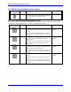
E24 - E27: Encoder Single-Ended/Differential Control
E Point and
Physical Layout
Location Description Default
E24
D2 ENC 4 through 1:
Jump pin 1 to 2 to tie complementary encoder
inputs to 2.5V.
1-2 Jumper
installed for E24 -
E27.
E25
D2 Jump pin 2 to 3 to tie complementary encoder
inputs to 5V.
For no encoder connection: Jump pin 1 to 2.
E24: ENC 4
E25: ENC 3
E26: ENC 2
E27: ENC 1
E26
D2 For single-ended encoders: Jump pin 1 to 2.
For differential line-driver encoders: Do not care.
E27
D2 For complementary open-collector encoders: Jump
pin 2 to 3.