
Reference Manual


PMAC 2 Software Reference
20 PMAC I-Variable Specifiation
Typically multiple PMAC2 boards on the same serial cable will share servo and phase
clock signals over the serial port cable for tight synchronization. If the servo and phase
clock lines are connected between multiple PMACs, only one of the PMAC boards can be
set up to output these clocks (E40 – E43 all ON for a PMAC(1), E1 jumper OFF for a
PMAC2). All of the other boards in the chain must be set up to input these clocks (one or
more of the jumpers E40 – E43 OFF for a PMAC(1), E1 jumper ON for a PMAC2).
Note:
Any PMAC(1) board with one or more of E40 – E43 OFF, or any
PMAC2 board with jumper E1 ON, is expecting its SERVO and
PHASE clock signals externally from a Card 0. If it does not
receive these clock signals, the watchdog timer will immediately
shut down the board and the red LED will light.
If the PMAC2 has E1 ON to receive external SERVO and PHASE clock signals for
synchronization purposes, but is not using multi-drop serial communications, I0 does not
need to be changed from 0.
To set up a board to communicate as Card 1 to Card 15 on a multi-drop serial cable, first
communicate with the board as Card 0. Set I0 to specify the card number (software
address) that the board will have on the multi-drop cable. Also, set I1 to 2 to enable the
serial software addressing. Store these values to the non-volatile flash memory with the
SAVE command. Then turn off power; if the board is to input its clocks, put a jumper on
E1; connect the multi-drop cable; restore power to the system.
I1 Serial Port Mode
Range
0 .. 3
Units
none
Default
0
Remarks
I1 controls two aspects of how PMAC uses its serial port. The first aspect is whether
PMAC uses the CS (CTS) handshake line to decide if it can send a character out the serial
port. The second aspect is whether PMAC will require software card addressing,
permitting multiple cards to be daisychained on a single serial line.
There are four possible values of I1, covering all the possible combinations:
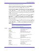
Setting Meaning
0 CS handshake used; no software card address required
1 CS handshake not used; no software card address required
2 CS handshake used; software card address required
3 CS handshake not used; software card address required
When CS handshaking is used (I1 is 0 or 2), PMAC waits for CS to go true before it will
send a character. This is the normal setting for real serial communications to a host; it
allows the host to hold off PMAC messages until it is ready.
When CS handshaking is not used (I1 is 1 or 3), PMAC disregards the state of the CS input
and always sends the character immediately. This mode permits PMAC to “output”
messages, values, and acknowledgments over the serial port even when there is nothing
connected, which can be valuable in stand-alone and PLC-based applications where there
are SEND and CMD statements in the program. If these strings cannot be sent out the
serial port, they can “back up”, stopping program execution.