
User's Manual


Turbo PMAC PCI HRM
Machine Connections 35
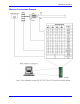
The J2 (JPAN) connector is a 26-pin connector with dedicated control inputs, dedicated indicator outputs, a
quadrature encoder input, and an analog input. The control inputs are low true with internal pull-up
resistors. They have predefined functions unless the control-panel-disable I-variable (I2) has been set to 1.
If this is the case, they may be used as general-purpose inputs by assigning M-variable to their
corresponding memory-map locations (bits of Y address $78800).
Command Inputs
JOG-/, JOG+/, PREJ/ (return to pre-jog position), and HOME/ affect the motor selected by the FDPn/ lines
(see below). The ones that affect a coordinate system are STRT/ (run), STEP/, STOP/ (abort), and HOLD/
(feed hold) affect the coordinate system selected by the FDPn/ lines.
Selector Inputs
The four low-true BCD-coded input lines FDP0/ (LSBit), FDP1/, FDP2/, and FDP3/ (MSBit) form a low-
true BCD-coded nibble that selects the active motor and coordinate system (simultaneously). Usually, these
are controlled from a single 4-bit motor/coordinate-system selector switch. The motor selected with these
input lines will respond to the motor-specific inputs. It will also have its position following function turned
on (Ix06 is set to 1 automatically); the motor just de-selected has its position following function turned off
(Ix06 is set to 0 automatically).
It is not a good idea to change the selector inputs while holding one of the jog inputs low. Releasing the jog
input then will not stop the previously selected motor. This can lead to a dangerous situation.
Alternate Use
The discrete inputs can be used for parallel-data servo feedback or master position if I2 has been set to 1.
The Acc-39 Handwheel Encoder Interface board provides 8-bit parallel counter data from a quadrature
encoder to these inputs. Refer to the Parallel Position Feedback Conversion section in the Acc-39 User
manual for more details on processing this data.
Reset Input
Input INIT/ (reset) affects the entire card. It has the same effect as cycling power or a host $$$ command.
It is hard-wired, so it retains its function even if I2 is set to 1.
Handwheel Inputs
The handwheel inputs HWCA and HWCB can be connected to the second encoder counter on PMAC with
jumpers E22 and E23. If these jumpers are on, nothing else should be connected to the Encoder 2 inputs.
The signal can be interpreted either as quadrature or as pulse (HWCA) and direction (HWCB), depending on
the value of I905. I905 also controls the direction sense of this input. Make sure that the Encoder 2 jumper
E26 is set for single ended signals, connecting pins 1 and 2.
Optional Voltage to Frequency Converter
The WIPER analog input (0 to +10V on PMAC PCI referenced to digital ground) provides an input to a
voltage-to-frequency converter (V/F) with a gain of 25 kHz/Volt, providing a range of 0-250 kHz. The
output of the V/F can be connected to the Encoder 4 counter using jumpers E72 and E73. If these jumpers
are on, nothing else should be connected to the Encoder 4 inputs. Make sure that the Encoder 4 jumper E24
is set for single-ended signals, connecting pins 1 and 2. This feature requires Option-15.
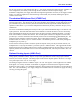
Frequency Decode
When used in this fashion, Encoder 4 must be set up for pulse-and-direction decode by setting I915 to 0 or
4. Usually, a value of 4 is used because with CHB4 (direction) unconnected, a positive voltage causes the
counter to count up. The encoder conversion table can then take the difference in the counter each servo
cycle and scale it, providing a value proportional to frequency, and therefore to the input voltage. Usually
this is used for feedrate override (time base control), but the resulting value can be used for any purpose.
The resulting value in the default setup can be found at X:$729,24
Power Supply