
User's Manual


Turbo PMAC PCI HRM
34 Machine Connections
Some amplifiers share the amplifier fault output with the amplifier enable\disable status output. In this case
a special PLC code must be written with the following sequence: disable the amplifier fault input (see Ix25),
enable the motor (J/ command), wait for the amplifier fault input to be false (monitor Mx23), re-enable the
amplifier fault input (see Ix25).
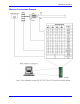
General-Purpose Digital Inputs and Outputs (JOPTO Port)
PMAC’s J5 or JOPTO connector provides eight general-purpose digital inputs and eight general-purpose
digital outputs. Each input and each output has its own corresponding ground pin in the opposite row. The
34-pin connector was designed for easy interface to OPTO-22 or equivalent optically isolated I/O modules.
Acc-21F is a six-foot cable for this purpose. Characteristics of the JOPTO port on the PMAC PCI:
• 16 I/O points. 100 mA per channel, up to 24V
• Hardware selectable between sinking and sourcing in groups of eight; default is all sinking (inputs can
be changed simply by moving a jumper; sourcing outputs must be special-ordered or field-configured)
• Eight inputs, eight outputs only; no changes. Parallel (fast) communications to PMAC CPU
• Not opto-isolated; easily connected to Opto-22 (PB16) or similar modules through ACC-21F cable
Jumper E7 controls the configuration of the eight inputs. If it connects pins 1 and 2 (the default setting), the
inputs are biased to +5V for the OFF state and they must be pulled low for the ON state. If E7 connects pins
2 and 3, the inputs are biased to ground for the OFF state, and must be pulled high for the ON state. In either
case, a high voltage is interpreted as a 0 by the PMAC software, and a low voltage is interpreted as a 1.
Caution:
Having Jumpers E1 and E2 set wrong can damage the IC. The +V output on this connector
has a 2A fuse, F1, for excessive current protection.
PMAC is shipped standard with a ULN2803A sinking (open-collector) output IC for the eight outputs.
These outputs can sink up to 100 mA and have an internal 3.3 kΩ pull-up resistor to go high (RP18). Do not
connect these outputs directly to the supply voltage, or damage to the PMAC will result from excessive
current draw. A high-side voltage (+5 to +24V) can be provided into Pin 33 of the JOPTO connector, and
this can be allowed to pull up the outputs by connecting pins 1 and 2 of Jumper E1. Jumper E2 must also
connect pins 1 and 2 for a ULN2803A sinking output.
It is possible for these outputs to be sourcing drivers by substituting a UDN2981A IC for the ULN2803A.
This U13 IC is socketed, and so may be replaced easily. For this driver, the internal resistor packs pull
down instead. With a UDN2981A driver IC, Jumper E1 must connect pins 2 and 3, and Jumper E2 must
connect pins 2 and 3.
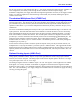
The outputs can be configured individually to a different output voltage by removing the internal pull-up
resistor pack RP18 and connecting to each output a separate external pull-up resistor to the desired voltage
level.
Example: Standard configuration using the ULN2803A sinking (open-collector) output IC
Control-Panel Port I/O (JPAN Port)