
User's Manual


Turbo PMAC PCI HRM
32 Machine Connections
Incremental Encoder Connection
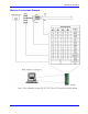
Each JMACH connector provides two +5V outputs and two logic grounds for powering encoders and other
devices. The +5V outputs are on pins 1 and 2; the grounds are on pins 3 and 4. The encoder signal pins are
grouped by number. All those numbered 1 (CHA1, CHA1/, CHB1, CHC1, etc.) belong to encoder #1. The
encoder number does not have to match the motor number, but usually does. If the PMAC is not plugged
into a bus and drawing its +5V and GND from the bus, use these pins to bring in +5V and GND from the
power supply. Connect the A and B (quadrature) encoder channels to the appropriate terminal block pins.
For encoder 1, the CHA1 is pin 25, CHB1 is pin 21. If it is a single-ended signal, leave the complementary
signal pins floating -- do not ground them. However, if single-ended encoders are used, please check the
settings of the jumpers E18 to E21 and E24 to E27. For a differential encoder, connect the complementary
signal lines -- CHA1/ is pin 27, and CHB1/ is pin 23. The third channel (index pulse) is optional; for
encoder 1, CHC1 is pin 17, and CHC1/ is pin 19.
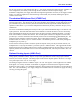
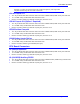
Example: differential quadrature encoder connected to channel #1:
DAC Output Signals
If PMAC is not performing the commutation for the motor, only one analog output channel is required to
command the motor. This output channel can be either single-ended or differential, depending on what the
amplifier is expecting. For a single-ended command using PMAC channel 1, connect DAC1 (pin 43) to the
command input on the amplifier. Connect the amplifier's command signal return line to PMAC's AGND
line (pin 58). In this setup, leave the DAC1/ pin floating; do not ground it.
For a differential command using PMAC channel 1, connect DAC1 (pin 43) to the plus command input on
the amplifier. Connect DAC1/ (pin 45) to the minus-command input on the amplifier. PMAC's AGND
should still be connected to the amplifier common. If the amplifier is expecting separate sign and magnitude
signals, connect DAC1 (pin 43) to the magnitude input. Connect AENA1/DIR1 (pin 47) to the sign
(direction input). Amplifier signal returns should be connected to AGND (pin 58). This format requires
some parameter changes on PMAC; (see Ix25. Jumper E17 controls the polarity of the direction output; this
may have to be changed during the polarity test. This magnitude-and-direction mode is suited for driving
servo amplifiers that expect this type of input, and for driving voltage-to-frequency (V/F) converters, such as
PMAC’s Acc-8D Option 2 board, for running stepper motor drivers.
If using PMAC to commutate the motor, use two analog output channels for the motor. Each output may be
single-ended or differential, just as for the DC motor. The two channels must be consecutively numbered,
with the lower-numbered channel having an odd number (e.g., use DAC1 and DAC2 for a motor, or DAC3
and DAC4, but not DAC2 and DAC3, or DAC2 and DAC4). For our motor #1 example, connect DAC1 (pin
43) and DAC2 (pin 45) to the analog inputs of the amplifier. If using the complements as well, connect
DAC1/ (pin 45) and DAC2/ (pin 46) to the minus-command inputs; otherwise leave the complementary
signal outputs floating. To limit the range of each signal to +/- 5V, use parameter Ix69. Any analog output
not used for dedicated servo purposes may be utilized as a general-purpose analog output. Usually, this is
done by defining an M-variable to the digital-to-analog-converter register (suggested M-variable definitions
M102, M202, etc.), then writing values to the M-variable. The analog outputs are intended to drive high-
impedance inputs with no significant current draw. The 220Ω output resistors will keep the current draw
lower than 50 mA in all cases and prevent damage to the output circuitry, but any current draw above 10 mA
can result in noticeable signal distortion.