
User's Manual


Turbo PMAC PCI HRM
Main Board E-Point Descriptions 27
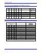
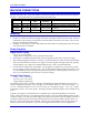
E109: Reserved for Future Use
E Point and
Physical Layout
Location Description Default
E109
B6 For future use. No jumper
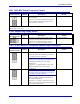
E110: Serial Port Configure
E Point and
Physical Layout
Location Description Default
E110
A7 Jump pin 1 to 2 for use of the J4 connector as RS-
232. Jump pin 2 to 3 for use of the J4 connector as
RS-422.
1-2 Jumper installed
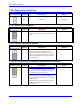
E111: Clock Lines Output Enable
E Point and
Physical Layout
Location Description Default
E111
A7 Jump pin 1 to 2 to enable the Phase, Servo and Init
lines on the J4 connector. Jump pin 2 to 3 to
disable the Phase, Servo and Init lines on the J4
connector. E111 on positions 1 to 2 is necessary
for daisy-chained PMACs sharing the clock lines
for synchronization.
2-3 Jumper installed
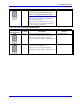
E114 - E115: Motors 5-8 Amplifier Enable Output Configure
E Point and
Physical Layout
Location Description Default
E114
A3
Caution:
The jumper setting must match the type of driver
IC, or damage to the IC will result.
Jump pin 1 to 2 to apply A+15V/A+V (as set by
E100) to pin 10 of U53 AENAn and EQUn
driver IC (should be ULN2803A for sink output
configuration).
Jump pin 2 to 3 to apply GND to pin 10 of U53
(should be UDN2981A for source output
configuration).
1-2 Jumper installed