
User's Manual


Turbo PMAC PCI HRM
26 Main Board E-Point Descriptions
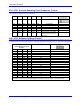
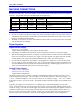
E98: DAC/ADC Clock Frequency Control
E Point and
Physical Layout
Location Description Default
E98
A4 Jump 1-2 to provide a 2.45 MHz DCLK signal to
DACs and ADCs.
Jump 2-3 to provide a 1.22 MHz DCLK signal to
DACs and ADCs. Important for high accuracy
A/D conversion on ACC-28.
1-2 Jumper installed
Note: This also divides the phase and servo clock frequencies in half.
See E29-E33, E3-E6, I10
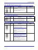
E100: Output Flag Supply Select
E Point and
Physical Layout
Location Description Default
E100
A3 Jump pin 1 to 2 to apply analog supply voltage
A+15V to U37 and U53 flag output driver IC.
Jump pin 2 to 3 to apply flag supply voltage
OPT+V to U37 and U53 flag output driver IC.
1-2 Jumper installed
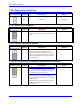
E101 - E102: Motors 1-4 Amplifier Enable Output Configure
E Point and
Physical Layout
Location Description Default
E101
A3
Caution:
The jumper setting must match the type of driver
IC, or damage to the IC will result.
Jump pin 1 to 2 to apply A+15V/A+V (as set by
E100) to pin 10 of U37 AENAn and EQUn driver
IC (should be ULN2803A for sink output
configuration).
Jump pin 2 to 3 to apply GND to pin 10 of U37
(should be UDN2981A for source output
configuration).
1-2 Jumper installed
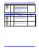
E102
A3
Caution:
The jumper setting must match the type of driver
IC, or damage to the IC will result.
Jump pin 1 to 2 to apply GND to pin 10 of U37
AENAn and EQUn (should be ULN2803A for
sink output configuration).
Jump pin 2 to 3 to apply A+15V/A+V (as set by
E100) to pin 10 of U37 (should be UDN2981A for
source output configuration).
1-2 Jumper installed