
User's Manual


Turbo PMAC PCI HRM
Jumper Summary 11
PCI Bus Base Address Control – The selection of the base address of the card in the I/O space of
the host PC’s expansion bus is assigned automatically by the operating system and it is not selected
through a jumper configuration.
E49: Serial Communications Parity Control – Jump pin 1 to 2 for no serial parity; remove jumper
for ODD serial parity.
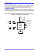
E54-E65: Interrupt Source Control – These jumpers control which signals are tied to interrupt lines
IR5, IR6 and IR7 on PMAC’s programmable interrupt controller (PIC), as shown in the interrupt
diagram. Only one signal may be tied into each of these lines.
E110: Serial Port Configure – Jump pin 1 to 2 for use of the J4 connector as RS-232. Jump pin 2 to
3 for use of the J4 connector as RS-422.
E111: Clock Lines Output Enable – Jump pin 1 to 2 to enable the Phase, Servo and Init lines on the
J4 connector. Jump pin 2 to 3 to disable the Phase, Servo and Init lines on the J4 connector. E111 on
positions one to two is necessary for daisy-chained PMACs sharing the clock lines for
synchronization.
I/O Configuration Jumpers
Caution:
A wrong setting of these jumpers will damage the associated output IC.
E1-E2: Machine Output Supply Configure – With the default sinking output driver IC
(ULN2803A or equivalent) in U13 for the J5 JOPTO port outputs, these jumpers must connect pins 1
and 2 to supply the IC correctly. If this IC is replaced with a sourcing output driver IC (UDN2981A
or equivalent), these jumpers must be changed to connect pins 2 and 3 to supply the new IC correctly.
E7: Machine Input Source/Sink Control – With this jumper connecting pins 1 and 2 (default), the
machine input lines on the J5 JOPTO port are pulled up to +5V or the externally provided supply
voltage for the port. This configuration is suitable for sinking drivers. If the jumper is changed to
connect pins 2 and 3, these lines are pulled down to GND. This configuration is suitable for sourcing
drivers.
E17A - E17D: Motors 1-4 Amplifier-Enable Polarity Control – Jumpers E17A through E17D
control the polarity of the amplifier enable signal for the corresponding motor 1 to 4. When the
jumper is on (default), the amplifier-enable line for the corresponding motor is low true so the enable
state is low-voltage output and sinking current, and the disable state is not conducting current. With
the default ULN2803A sinking driver used by the PMAC PCI on U37, this is the fail-safe option,
allowing the circuit to fail in the disable state. With this jumper off, the amplifier-enable line is high
true so the enable state is not conducting current, and the disable state is low-voltage output and
sinking current. This setting is not generally recommended.
E17E - E17H: Motors 5-8 Amplifier-Enable Polarity Control – Jumpers E17A through E17D
control the polarity of the amplifier enable signal for the corresponding motor 5 to 8. When the
jumper is on (default), the amplifier-enable line for the corresponding motor is low true so the enable
state is low-voltage output and sinking current, and the disable state is not conducting current. With
the default ULN2803A sinking driver used by the PMAC PCI on U53, this is the fail-safe option,
allowing the circuit to fail in the disable state. With this jumper off, the amplifier-enable line is high
true so the enable state is not conducting current and the disable state is low-voltage output and
sinking current. This setting is not generally recommended.