
User's Manual


Turbo PMAC PCI HRM
Introduction 3
• Option 5D2 provides a 100 MHz CPU (150 MHz PMAC equivalent), an expanded 512k x 24 of
compiled/assembled program memory, 128k x 24 of user data memory, and a 2M x 8 flash
memory.
• Option 5D3 provides a 100 MHz CPU (150 MHz PMAC equivalent), an expanded 512k x 24 of
compiled/assembled program memory, an expanded 512k x 24 of user data memory, and a 4M x
8 flash memory.
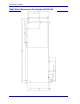
Option 7: Plate Mounting
Option 7 provides a mounting plate connected to the PMAC with standoffs. It is used to install the
PMAC in standalone applications.
Option 8: High-Accuracy Clock Crystal
The Turbo PMAC PC has a clock crystal (component Y1) of nominal frequency 19.6608 MHz (~20
MHz). The standard crystal’s accuracy specification is +/-100 ppm.
• Option 8A provides a nominal 19.6608 MHz crystal with a +/-15 ppm accuracy specification.
Option 9T: Auxiliary Serial Port
Option 9T adds an auxiliary RS-232 port on the CPU piggyback board. The key components added
are IC U22 and connector J8 on the CPU board.
Option 10: Firmware Version Specification
Normally the Turbo PMAC PC is provided with the newest released firmware version. A label on the
U10 flash memory IC shows the firmware version loaded at the factory.
• Option 10 provides for a user-specified firmware version.
Option 12: Analog-to-Digital Converters
• Option 12 permits the installation of 8 or 16 channels of on-board multiplexed analog-to-digital
converters. One or two of these converters are read every phase interrupt. The analog inputs are
not optically isolated, and each can have a 0 – 5V input range, or a +/-2.5V input range,
individually selectable.
• Option 12 provides an 8-channel 12-bit A/D converter. The key components on the board are
U20 and connector J30.
• Option 12A provides an additional 8-channel 12-bit A/D converter. The key component on the
board is U22.
Option 15: V-to-F Converter for Analog Input
The JPAN control panel port on the Turbo PMAC PC has an optional analog input called Wiper
(because it is often tied to a potentiometer’s wiper pin). Turbo PMAC PC can digitize this signal by
passing it through an optional voltage-to-frequency converter, using E-point jumpers to feed this into
the Encoder 4 circuitry (no other use is then permitted), and executing frequency calculations using
the time base feature of the encoder conversion table.
• Option 15 provides a voltage-to-frequency converter that permits the use of the Wiper input on
the control panel port.
Option 16: Battery-Backed Parameter Memory
The contents of the standard memory are not retained through a power-down or reset unless they have
been saved to flash memory first. Option 16 provides supplemental battery-backed RAM for real-
time parameter storage that is ideal for holding machine state parameters in case of an unexpected
power-down. The battery is located at component BT1.
• Option 16A provides a 32k x 24 bank of battery-backed parameter RAM in components U17,
U18, and U19, fitting in the smaller footprint for those locations.
• Option 16B provides a 128k x 24 bank of battery-backed parameter RAM in components U17,
U18, and U19, filling the full footprint for those locations.