
User's Manual

UMAC-CPCI Turbo CPU Board Hardware Reference Manual
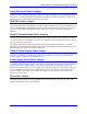
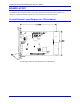
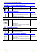
BOARD LAYOUT
This diagram of the Compact UMAC Turbo CPU board shows the locations of the jumpers and
connectors. Detailed information about each of the jumpers and connectors follows.
Current Revision Layout Diagram (rev 103 and above)
E25C
E1B
J4
J7
E23
E21
E22
E20
E18
E17
E1A
E18A
RP2
RP3
RP1
E18C
E18B
E18D
E11
E5
E3
E4
E2
J5
W1
J3
E19
E0
J10
E25B
E25A
F1
J12
J6
F2
J1
J2
J11
Current UMAC CPCI Turbo CPU Board Layout (rev 103 and above)
Board Layout 9