
User's Manual


PMAC VME Hardware Reference Manual
4 Introduction
The PV CPU has operational differences from earlier CPU configurations to support the new features.
The following paragraphs explain these differences and are only relevant if using the 602705 CPU
piggyback board on the controller.
Configurations
The PV CPU board is configured at the factory to the customer’s specifications. The JEXP expansion
port is buffered, providing the capability to connect many boards on the expansion port.
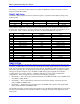
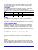
The following table shows the configuration of the key components on the PV CPU board for the PMAC2
VME.
Version Main Memory
Backup
U6, U9, U15
Components
U7, U10, U16
Components
U5 Components BT1 Components
Standard Flash Empty 32-pin RAM Flash ROM Empty
Opt 5B Flash Empty 32-pin RAM Flash ROM Empty
Opt 5C Flash Empty 32-pin RAM Flash ROM Empty
+Opt 16 Flash 28-pin RAM 32-pin RAM Flash ROM Battery
Firmware
The PV CPU board does not support firmware versions previous to V1.16 of August 1996 without
changes in programming of the on-board logic (GALs). If the firmware must be changed between a
version previous to V1.16 and a version V1.16 or newer, the on-board logic must be re-programmed.
When loading new firmware into the flash configurations of the PV CPU, E4 on the CPU board must be
ON in addition to having the PMAC2 VME re-initialization jumper E3 ON.
Option 16 Supplemental Memory
If the Option 16 supplemental battery-backed parameter memory is ordered, an extra bank of memory
with battery backup circuitry is provided. This option can be ordered only if the main memory is flash
backed (Option 4A, 5A, 5B, or 5C). This memory is for user parameter storage only. From PMAC
programs it can be accessed with M-variables only (L-variables also in compiled PLCs). The on-line
direct-memory read and write commands can be used from the host computer as well.
With M-variable access, arrays can be created with indirect addressing techniques by pointing a second
M-variable to the definition of a first M-variable that points into this memory area. For example, with the
M-variable definitions:
M0->L:$A000; 1st long word of Opt. 16 RAM; floating point
M10->Y:$BC000,0,16; Low 16 bits of M0 def., with pointer address
Note:
This technique is not possible with L-variables in compiled PLCs.
The following code segment could load a sine table into the first 360 words of the Option 16 RAM:
P1=0
WHILE (P1<360)
M10=$A000+P1 ; Sets address that M0 points to
M0=SIN(P1) ; Puts value in register that M0 points to
P1=P1+1
ENDWHILE
Physically, the Option 16 memory is a 16k x 24 bank of battery-backed static RAM. It maps into the
PMAC2 VME at addresses $A000 to $BFFF, on both the X and Y data buses, an 8k x 48 block of address
space. Addresses Y:$BC00 to Y:$BFFF are double-mapped with the main flash-backed RAM for the M-
variable definitions, and should not be used for user parameter storage.