
User's Manual


PMAC2 VME Hardware Reference Manual
Introduction 3
Alternately, you can define an M-variable such as M99->X:$FFFD,0,4 and then read from or write to
these bits with the M-variable.
PMAC2 VME Setup
On PMAC2 VME, jumpers E2 and E4 control the frequency of operation of the DSP according to the
following table:
E2 E4 X:$FFFD; 0-3 True Multiplier DSP Frequency
OFF OFF 1 x2 40 MHz
ON OFF 2 x3 60 MHz
OFF ON 3 x4 80 MHz
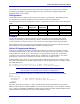
On the PMAC2 VME, I54 is read at power-up to set the baud rate clock. Because this clock is derived
from the CPU clock frequency, the proper setting of I54 is dependent on the CPU clock frequency as set
by E2 and E4. Table 1-3 shows the settings of I54 for 40, 60, and 80 MHz CPU operation.
I54 Baud Rate for 40 MHz CPU Baud Rate for 60 MHz CPU Baud Rate for 80 MHz CPU
0 600 Disabled 1200
1 900* (-0.05%) 900 1800* (-0.1%)
2 1200 1200 2400
3 1800* (-0.1%) 1800 3600* (-0.19%)
4 2400 2400 4800
5 3600* (-0.19%) 3600 7200* (-0.38%)
6 4800 4800 9600
7 7200* (-0.38%) 7200 14,400*(-0.75%)
8 9600 9600 19,200
9 14,400*(-0.75%) 14,400 28,800*(-1.5%)
10 19,200 19,200 38,400
11 28,800*(-1.5%) 28,800 57,600*(-3.0%)
12 38,400 38,400 76,800
13 57,600*(-3.0%) 57,600 115,200*(-6.0%)
14 76,800 76,800 153,600
15 Disabled 115,200 Disabled
* not an exact baud rate
PMAC2 CPUs
The PMAC2 VME CPU communicates with the axes through specially designed custom gate array ICs,
referred to as DSPGATES. Each of these ICs can handle four analog output channels, four encoders as
input, and four analog-derived inputs from accessory boards. One PMAC2 VME can utilize from one to
four of these gate array ICs, so specifying the hardware configuration amounts to counting the numbers
and types of inputs and outputs. Up to 16 PMAC2 VMEs may be ganged together with complete
synchronization, for a total of 128 axes. A PMAC2 VME may have one of three available CPU
configurations. These configurations are described in the following paragraphs.
• P/N 602398 — This is the original standard CPU board for the PMAC2 VME. It has a 20MHz clock
and a battery backup RAM.
• P/N 602405 — This is a flash memory CPU board with no battery backup. This board provides
either a 40MHz or 60MHz clock.
• P/N 602705 — The PV CPU piggyback board provides 80 MHz CPU operation and supplemental
battery-backed RAM for the PMAC2 VME.
The PV CPU board gets its name from the PV package style of the Motorola 56002 DSP IC on the board.
The board is also called the Universal CPU because it can support all speeds and configurations of the
CPU section.