
User's Manual


PMAC VME Hardware Reference Manual
2 Introduction
• Amplifier fault input
• Four supplementary flag inputs (T, U, V, W)
• Two inputs from serial analog-to-digital converters (ADCs)
• ADC clock and strobe signal outputs
The DSPGATE1 ASIC also generates several clock frequencies necessary for hardware and software
operation, under the user’s software control:
• PWM output frequency
• DAC clock frequency
• ADC clock frequency
• Encoder sample clock frequency
• Pulse-frequency modulation (PFM) clock frequency
• Phase interrupt clock frequency
• Servo interrupt clock frequency
Note:
Phase interrupt clock frequency and Servo interrupt clock frequency are generated
from the first DSPGATE1 only.
DSPGATE2 I/O ASIC
There is also a DSPGATE2 ASIC on PMAC2 VME, which is used for interface to other I/O. The
DSPGATE2 ASIC has three parts:
• General-purpose digital I/O: 56 I/O points for JIO, JTHW, and JDISP ports
• Servo interface circuitry for 2 supplemental channels with clock generation
• MACRO ring interface circuitry
Generally, the general-purpose I/O and the servo interface circuitry on the DSPGATE2 share pins, except
for two 2-channel encoder inputs and two PWM/PFM output sub-channels. On a PMAC2 VME board,
usually the shared pins are used for general-purpose I/O instead of extra servo interface circuitry, but this
is up to the individual user.
PMAC2 VME Board Configuration
Jumpers on the PMAC2 VME determine the frequency at which the DSP on the PV CPU board will
operate. The 56002 DSP has a phased-locked loop (PLL) that allows it to multiply the crystal frequency
by a programmable integer value, permitting very high CPU frequencies with a moderate crystal
frequency. The crystal frequency on the PV CPU board is always 19.6608 MHz, commonly called 20
MHz.
The component rating of the DSP IC specifies the highest frequency at which it safely can run, but it is
the multiplication factor typically set by jumpers that specifies the frequency at which it actually runs.
Usually this is a frequency at or near the maximum for the component.
It is safe to run a DSP at a frequency below the maximum. It may be possible to run a DSP at a frequency
higher than its maximum frequency, particularly at low ambient temperatures, but safe operation cannot
be guaranteed. Unpredictable and possibly dangerous operation may result.
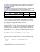
On power-up/reset, the DSP, operating at the crystal frequency of 20 MHz, reads the frequency jumpers
(E2 and E4) and writes into its own PLL multiplier register at X:$FFFD. Bits 0-3 of this word contain a
value one less than the multiplier value (if the frequency is being multiplied by 3, these bits contain a
value of 2).
If you wish to check the value of your multiplier, you can use the on-line command RHX:$FFFD and
look at the last hexadecimal digit. The actual multiplier is one greater than the value in this last digit.