
User's Manual


PMAC2 VME Hardware Reference Manual
PMAC2 VME CPU 37
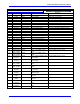
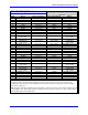
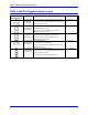
PMAC2 VME CPU Piggyback Board Jumpers
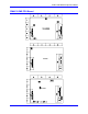
See the PMAC PC CPU Piggyback Board layout diagram for jumper locations.
E Point and
Physical Layout
Location Description Default
E1
D1 (602398)
A1 (602405)
B1 (602705)
Remove jumper to enable watchdog timer operation.
Jump pins 1 to 2 to disable watchdog timer operation
(for test purposes only).
No Jumper
E2
A2 (602398)
N/A (602405)
D5 (602705)
Remove jumper to disable extended channel
addressing (Channels 9-16).
Jump pins 1 to 2 to enable extended channel
addressing (Channels 9-16).
No Jumper
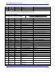
E3
C1 (602398)
N/A (602405)
D4 (602705)
Remove jumper (or no jumper present) to disable
extended channel addressing (Channels 9-16).
Jump pins 1 to 2 to enable extended channel
addressing (Channels 9-16).
No Jumper
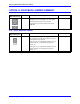
E4
A5 (602398)
N/A (602405)
B1 (602705)
Boot Enable Jumper.
Remove jumper for normal use.
Jump pins 1 and 2 for external firmware load (with
MAIN board E3 on).
No Jumper
E5
1
2
3
N/A (602398)
N/A (602405)
B3 (602705)
Battery-backed RAM Size Select.
Jump pins 2 and 3 for supple-mental battery-backed
memory (Option 16 only).
No Jumper if no battery-backed memory.
No Jumper