
User's Manual


PMAC2 VME Hardware Reference Manual
Option 1V Piggyback Jumper Summary 33
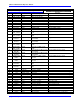
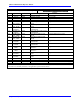
OPTION 1V PIGGYBACK JUMPER SUMMARY
See the Option 1V Piggyback board layout diagram for jumper locations.
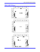
E Point and
Physical Layout
Location Description Default
JP1-1 to JP1-32
• • •
Jump pins 1 to 2 to use B-row of P2A connector for
JMACH pins (not compatible with 32-bit VME).
Remove jumpers to leave B-row of P2A
unconnected to prevent contention with 32-bit
VME Bus.
1-2 jumpers installed
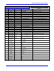
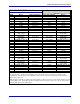
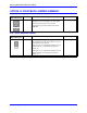
E14: SCLK Direction Control
E Point and
Physical Layout
Location Description Default
E14
Remove jumper to output SCLK generated in
second ASIC on SCLK _56 and SCLK _78, or to
control direction by software
Jump pins 1 to 2 to input SCLK signal for second
ASIC on SCLK _78 and output this signal on
SCLK _56
Jump pins 2 to 3 to input SCLK signal for second
ASIC on SCLK _56 and output this signal on
SCLK _78
No jumper installed