
User's Manual

PMAC2 VME Hardware Reference Manual
Jumper Summary 31
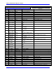
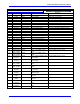
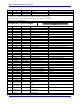
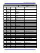
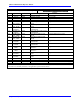
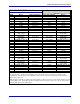
J12/JMACH4 (100-Pin Header)
1
2
99
1
00
Front View
Pin# Symbol Function Description Notes
81 AENA8+ Output Amplifier Enable High is enable
82 AENA8- Output Amplifier Enable Low is enable
83 FAULT8+ Input Amplifier Fault Programmable polarity
84 FAULT8- Input Amplifier Fault
85 PWMATOP8+
DAC_CLK8+
Output Phase A Top CMD or DAC
Clock
Programmable function control
86 PWMATOP8-
DAC_CLK8-
Output Phase A Top CMD or DAC
Clock
87 PWMABOT8+
DAC8A+
Output Phase A Bottom CMD or DAC
A Serial Data
Programmable function control
88 PWMABOT8-
DAC8A-
Output Phase A Bottom CMD or DAC
A Serial Data
89 PWMBTOP8+
DAC_STB8+
Output Phase B Top CMD or DAC
Strobe
Programmable function control
90 PWMBTOP8-
DAC_STB8-
Output Phase B Top CMD or DAC
Strobe
91 PWMBBOT8+
DAC8B+
Output Phase B Bottom CMD or DAC
B Serial Data
Programmable function control
92 PWMBBOT8-
DAC8B-
Output Phase B Bottom CMD or DAC
B Serial Data
93 PWMCTOP8+
DIR8+
Output Phase B Top CMD or PFM
Direction
Programmable function control
94 PWMCTOP8-
DIR8-
Output Phase B Top CMD or PFM
Direction
95 PWMCBOT8+
PULSE8+
Output Phase B Bottom CMD or PFM
Pulse
Programmable function control
96 PWMCBOT8-
PULSE8-
Output Phase B Bottom CMD or PFM
Pulse
97 GND Common Reference Voltage
98 GND Common Reference Voltage
99 +5V Output / Input +5V Power For external circuit or from external supply
100 +5V Output / Input +5V Power
The JMACH4 connector provides the interface pins for channels 7 and 8. Usually, it is connected to a breakout board, such
as one of the Acc-8x family of boards, or an application-specific interface board.