
User's Manual

PMAC2 VME Hardware Reference Manual
Jumper Summary 25
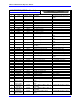
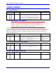
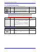
E17 - E18: Serial Connector Select
E17 and E18 control whether the RS-232 or RS-422 serial port is used.
E Point and
Physical Layout
Location Description Default
E17
B2 Jump pins 1 to 2 to use RS-232 serial interface.
Jump pins 2 to 3 to use RS -422 serial interface
1-2 jumper installed
E18
C2 Jump pins 1 to 2 to use RS -232 serial interface.
Jump pins 2 to 3 to use RS -422 serial interface
1-2 jumper installed
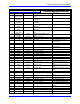
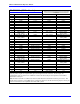
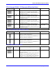
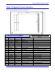
E20A-I: DPRAM Byte Order Control
Caution:
All E20A-I jumpers must be in the same setting for DPRAM communications to
work.
E Point and
Physical Layout
Location Description Default
E20
A 5 (4 3) (2 1)
B 5 (4 3) (2 1)
C 5 (4 3) (2 1)
D 5 (4 3) (2 1)
E 5 (4 3) (2 1)
F 5 (4 3) (2 1)
G 5 (4 3) (2 1)
H 5 (4 3) (2 1)
I 5 (4 3) (2 1)
C4
C4
C4
C4
C4
D4
D4
D4
D4
Jump pins 1 to 2, and pins 3 to 4, to tie DPRAM data
lines 8-15 to VME Bus data lines 8-15, and DPRAM
data lines 0-7 to VME Bus data lines 0-7 (Motorola
big-endian format)
Jump pins 2 to 3, and pins 4 to 5 to tie DPRAM data
lines 8-15 to VME Bus data lines 0-7, and DPRAM
data lines 0-7 to VME Bus data lines 8-15 (Intel little-
endian format)
1-2, 3-4 jumpers
installed (Motorola
format)
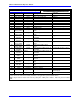
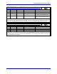
E39: Reset-From-Bus Enable
E Point and
Physical Layout
Location Description Default
E39
D1 Jump pin 1 to 2 to permit VME Bus reset line to reset
PMAC2.
Remove jumper so VME Bus reset line does not reset
PMAC2.
1-2 jumper installed