
User's Manual

PMAC VME Hardware Reference Manual
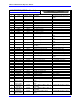
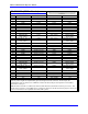
24 Jumper Summary
E7A-H through E10A-H: P2 Connector B-Row Use Select
E Point and
Physical Layout
Location Description Default
E7A-H
B5 Jump pins 1 to 2 to use B-row of P2 connector for
JMACH pins (not compatible with 32-bit VME).
Jump pins 2 to 3 to use B-row of P2 connector for 32-
bit VME bus interface
1-2 jumpers installed
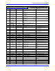
E8A-H
B5 Jump pins 1 to 2 to use B-row of P2 connector for
JMACH pins (not compatible with 32-bit VME).
Jump pins 2 to 3 to use B-row of P2 connector for 32-
bit VME bus interface
1-2 jumpers installed
E9A-H
A5 Jump pins 1 to 2 to use B-row of P2 connector for
JMACH pins (not compatible with 32-bit VME).
Jump pins 2 to 3 to use B-row of P2 connector for 32-
bit VME bus interface
1-2 jumpers installed
E10A-H
A5 Jump pins 1 to 2 to use B-row of P2 connector for
JMACH pins (not compatible with 32-bit VME).
Jump pins 2 to 3 to use B-row of P2 connector for 32-
bit VME bus interface
1-2 jumpers installed
(32-bit VME)
Note: All jumpers in the E7 to E10 families must be in the same setting.
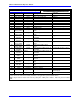
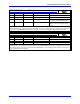
E11-E12: JEQU Port Sink/Source Select
E Point and
Physical Layout
Location Description Default
E11
A1 Jump pins 1 to 2 for sinking driver (ULN2803A) on
JEQU port (default configuration).
Jump pins 2 to 3 for sourcing driver (UDN2981A) on
JEQU port (alternate configuration).
1-2 jumpers installed
E12
A1 Jump pins 1 to 2 for sinking driver (ULN2803A) on
JEQU port (default configuration).
Jump pins 2 to 3 for sourcing driver (UDN2981A) on
JEQU port (alternate configuration).
1-2 jumpers installed
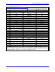
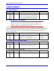
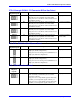
E13: SCLK Direction Control
E Point and
Physical
Layout
Location Description Default
E13
A1 Remove jumper to output SCLK generated in first
ASIC on SCLK_12 and SCLK_34, or to control
direction by software.
Jump pins 1 to 2 to input SCLK signal for first ASIC
on SCLK_34 and output this signal on SCLK_12.
Jump pins 2 to 3 to input SCLK signal for first ASIC
on SCLK_12 and output this signal on SCLK_34.
No jumper installed