
User's Manual

PMAC2 VME Hardware Reference Manual
Jumper Summary 23
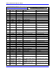
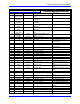
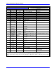
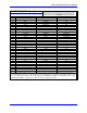
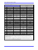
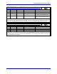
JUMPER SUMMARY
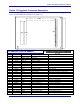
See PMAC2 VME layout diagram for jumper locations.
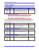
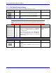
E1: Card 0 Select
E Point and
Physical Layout
Location Description Default
E1
B1 Remove jumper to specify that this is Card 0, which
generates its own phase and servo clock (default).
Jump pins 1 to 2 to specify that this is not card 0, but
Card 1 to F (15), which requires external phase and
servo clock signals from the serial port to operate.
No jumper installed
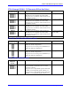
E2: 40 MHz/60 MHz CPU Operation
Caution:
Operation of a board with 40 MHz components (standard) at 60 MHz is done
completely at the user’s own risk; Delta Tau can accept no responsibility for the
operation of PMAC2 or the machine under these conditions.
It may be possible to operate a board with 40 MHz components (standard) at 60 MHz under some
conditions by changing the setting of jumper E2. However, this operates the components outside of their
specified operating range, and proper execution of PMAC2 under these conditions is not guaranteed.
PMAC software failure is possible, even probable, under these conditions, and this can lead to very
dangerous machine failure.
E Point and
Physical Layout
Location Description Default
E2
B2 Remove jumper to specify 40 MHz operation of the
PMAC CPU (2 x crystal frequency).
Jump pins 1 to 2 to specify 60 MHz operation of the
PMAC CPU (3 x crystal frequency).
No jumper installed
(standard)
1-2 jumper installed
(Option 5B)
E3: Re-Initialization on Reset Control
E Point and
Physical Layout
Location Description Default
E3
B2 Remove jumper for normal reset mode (default).
Jump pins 1 to 2 for re-initialization on reset.
No jumper installed
E4 - E6: (Reserved for future use)
E Point and
Physical Layout
Location Description Default
E4 - E6
B2 No jumper installed