
User's Manual

PMAC VME Hardware Reference Manual
22 Connectors
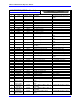
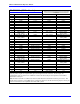
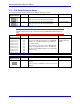
TB1 (2/4-Pin Terminal Block)
Pin# Symbol Function Description Notes
1 GND Common Reference Voltage
2 +5V Input Positive Supply Voltage Supplies all PMAC digital circuits
3 +12V Input Positive Supply Voltage +12v to +15v; not required on-board;
used on j1 to supply analog inputs
4 -12V Input Negative Supply Voltage -12V to –15V; required for Opt-12
ADCs; used on J1 to supply analog
inputs
This terminal block can be used to provide the input for the power supply for the circuits on the PMAC2 board
when it is not in a bus configuration. When the PMAC2 is in a bus configuration, these supplies come through the
bus connector automatically from the bus power supply; in this case, this terminal block should not be used.
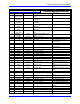
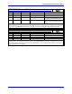
TB2 (3-Pin Terminal Block)
Pin# Symbol Function Description Notes
1 WD_NC Output Watchdog Relay Out Normally closed
2 COM Input Watchdog Return +V or 0V
3 WD_NO Output Watchdog Relay Out Normally open
4 COM Input Watchdog Return +V or 0V
This terminal block provides the output for PMAC2’s watchdog timer relay, both normally open and normally
closed contacts. The normally closed relay contact is open while PMAC2 is operating properly (it has power and
the watchdog timer is not tripped) and closed when the PMAC2 is not operating properly (either it has lost power
or the watchdog timer has tripped).