
User's Manual

PMAC VME Hardware Reference Manual
20 Connectors
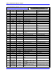
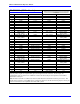
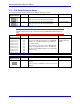
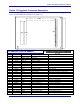
P1 JMACH (96-Pin Header)
Front View
Pin # Row A Row B Row C
01 D00 BBSY/ D08
02 D01 BCLR/ D09
03 D02 ACFAIL/ D10
04 D03 B0IN/ D11
05 D04 BG0OUT/ D12
06 D05 BG1IN/ D13
07 D06 BG1OUT/ D14
08 D07 BG2IN/ D15
09 GND BG2OUT/ GND
10 SYSCLK BG3IN/ SYSFAIL/
11 GND BG3OUT/ BERR/
12 DS1/ BR0/ SYSRESET/
13 DS0/ BR1/ LWORD/
14 WRITE/ BR2/ AM5
15 GND BR3/ A23
16 DTACK/ AM0 A22
17 GND AM1 A21
18 AS/ AM2 A20
19 GND AM3 A19
20 IACK/ GND A18
21 IACKIN/ SERCLK A17
22 IACKOUT/ SERDAT/ A16
23 AM4 GND A15
24 A07 IRQ7/ A14
25 A06 IRQ6/ A13
26 A05 IRQ5/ A12
27 A04 IRQ4/ A11
28 A03 IRQ3/ A10
29 A02 IRQ2/ A09
30 A01 IRQ1/ A08
31 -12V +5V STDBY +12V
32 +5V +5V +5V
This is the standard VME connector. It is sufficient for 16-bit or 24-bit addressing and for 8-bit or 16-bit data.
For 32-bit addressing the b-row of P2 must be used as well. PMAC does not support 32-bit data transfers over the
bus, even with the b-row of P2. If P1 is connected to the VME backplane, PMAC is connected to the +5V supply
and GND automatically. In this case, no other +5V supply should be connected.