
User's Manual


PMAC VME Hardware Reference Manual
12 Connectors
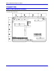
J5A/JRS422 (26-Pin Header)
Front View
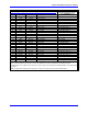
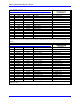
Pin # Symbol Function Description Notes
1 CHASSI Common PMAC Common
2 S+5V Output +5Vdc Supply
3 RD- Input Receive Data Diff. I/O Low True **
4 RD+ Input Receive Data Diff. I/O High True *
5 SD- Output Send Data Diff. I/O Low True **
6 SD+ Output Send Data Diff. I/O High True *
7 CS+ Input Clear to Send Diff. I/O High True **
8 CS- Input Clear to Send Diff. I/O Low True *
9 RS+ Output Req. to Send Diff. I/O High True **
10 RS- Output Req. to Send Diff. I/O Low True *
11 DTR Bidirect Data Term Read Tied to DSR
12 INIT/ Input PMAC Reset Low is Reset
13 GND Common PMAC Common **
14 DSR Bidirect Data Set Ready Tied to DTR
15 SDIO- Bidirect Special Data Diff. I/O Low True
16 SDIO+ Bidirect Special Data Diff. I/O High True
17 SCIO- Bidirect Special Ctrl. Diff. I/O Low True
18 SCIO+ Bidirect Special Ctrl. Diff. I/O High True
19 SCK- Bidirect Special Clock Diff. I/O Low True
20 SCK+ Bidirect Special Clock Diff. I/O High True
21 SERVO- Bidirect Servo Clock Diff. I/O Low True ***
22 SERVO+ Bidirect Servo Clock Diff. I/O High True ***
23 PHASE- Bidirect Phase Clock Diff. I/O Low True ***
24 PHASE+ Bidirect Phase Clock Diff. I/O High True ***
25 GND Common PMAC Common
26 +5V Output +5vdc Supply Power supply out
This connector can be used for serial communications on a PMAC2 VME if E17 and E18 jumpers connect pins 2
and 3. If these jumpers connect pins 1 and 2, the J5 RS-232 connector should be used instead for serial
communications. In addition, this connector is used to daisy chain interconnect multiple PMACs for synchronized
operation.
Note: Jumpers E17 and E18 must connect pins 2 and 3 to use this port for serial communications.