
Reference Manual

PMAC 2 Software Reference
58 PMAC I-Variable Specifiation
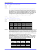
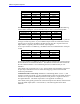
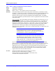
When commanding in this mode over the MACRO ring, the address specified is that of
Register 0 for the MACRO node. The following table shows these addresses:
Channel Address Channel Address
Node 0 Reg. 0 $C0A0 Node 8 Reg. 0 $C0B0
Node 1 Reg. 0 $C0A4 Node 9 Reg. 0 $C0B4
Node 4 Reg. 0 $C0A8 Node 12 Reg. 0 $C0B8
Node 5 Reg. 0 $C0AC Node 13 Reg. 0 $C0BC
See Also Selecting the Output (Setting Up a Motor)
I-variables Ix01, Ix25, Ix70-Ix83
Memory-I/O registers Y:$C000-Y:$C03F
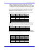
Ix03 Motor x Position Loop Feedback Address
Range
Extended legal PMAC “X” addresses
Units
Extended legal PMAC “X” addresses
Default
Variable PMAC(1),
PMAC2
Source with
Default Table
PMAC2
Ultralite
Source with
Default Table
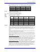
I103 $0720 Converted ENC1 $0721 Converted Node 0
I203 $0721 Converted ENC2 $0723 Converted Node 1
I303 $0722 Converted ENC3 $0725 Converted Node 4
I403 $0723 Converted ENC4 $0727 Converted Node 5
I503 $0724 Converted ENC5 $0729 Converted Node 8
I603 $0725 Converted ENC6 $072B Converted Node 9
I703 $0726 Converted ENC7 $072D Converted Node 12
I803 $0727 Converted ENC8 $072F Converted Node 13
Remarks
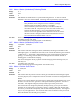
Ix03 tells the PMAC where to look for its feedback to close the position loop for Motor x.
Usually it points to an entry in the Encoder Conversion Table, where the values from the
encoder counter registers have been processed at the beginning of each servo cycle
(possibly to include sub-count data). This table starts at address $0720 and continues until
address $073F. It is shipped from the factory configured as shown in the default table
above.
For a motor with dual feedback (motor and load), use Ix03 to point to the encoder on the
load, and Ix04 to point to the encoder on the motor.
If the position loop feedback device is the same device as is used for commutation (with
PMAC doing the commutation), then it must also be specified for commutation with Ix83.
However, Ix83 should specify the address of the encoder counter itself, not the converted
data of the table.
Hardware Home Position Capture
: The source address of the position information occupies
bits 0 to 15 of Ix03 (range $0000 to $FFFF, or 0 to 65535). With bit 16 equal to zero – the
normal case – position capture on homing is done with the hardware capture register
associated with the flag inputs pointed to by Ix25. In this case, it is important to match the
encoder number, the address pointed to with Ix03, with the flag number, the address
pointed to with Ix03 (e.g. ENC1 – CHA1 & CHB1 – with HMFL1 and LIM1).
Software Home Position Capture
: If bit 16 (value 65536) is set to one, the position capture
on homing is done through software, and the position source does not have to match the
input flag source. This is particularly important for parallel-data position feedback, such
as from a laser interferometer (which is incremental data and requires homing). For
example, if motor #1 used parallel feedback from a laser interferometer processed as the
first (triple) entry in the conversion table, the key I-variables would be: