
Reference Manual

PMAC 2 Software Reference
56 PMAC I-Variable Specifiation
On PMAC(1) boards, if Ix01 is set to 0 and bit 16 of Ix02 is set to 1, then only the
magnitude of the command is written to the register specified by Ix02 (e.g. I103=$1C003
to use DAC1 in this mode); the sign of the command is written to bit 14 of the flag register
specified by Ix25, which is usually the AENA/DIR output. If this sign-and-magnitude
mode is used, bit 16 of Ix25 should be set to 1 so this bit is not used for the amplifier-
enable function. This mode is usually used with the ACC-8D Opt 2 voltage-to-frequency
converter to generate pulse-and-direction signals for stepper-motor drives. Sign-and-
magnitude mode is not available on PMAC2; for stepper applications it uses a fully
digitally generated pulse train as described below.
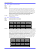
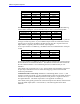
In PMAC2 systems, if a single analog output is desired for the servo, it is usually the A
DAC for the channel. The following table shows these addresses:
Channel Address Channel Address
DAC1A $C002 DAC9A $C042
DAC2A $C00A DAC10A $C04A
DAC3A $C012 DAC11A $C052
DAC4A $C01A DAC12A $C05A
DAC5A $C022 DAC13A $C062
DAC6A $C02A DAC14A $C06A
DAC7A $C032 DAC15A $C072
DAC8A $C03A DAC16A $C07A
Channels 9 – 16 are on an ACC-24P/V2 board. For B-channel DAC
registers, add 1 to the matching A-channel address
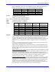
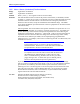
When using a PMAC2 Ultralite board to command the servo over the MACRO ring, the
command output is typically written to the MACRO node register 0. For the MACRO
Type 1 protocol used with Delta Tau MACRO Stations, the addresses are shown in the
following table:
Channel Address Channel Address
Node 0 Reg. 0 $C0A0 Node 8 Reg. 0 $C0B0
Node 1 Reg. 0 $C0A4 Node 9 Reg. 0 $C0B4
Node 4 Reg. 0 $C0A8 Node 12 Reg. 0 $C0B8
Node 5 Reg. 0 $C0AC Node 13 Reg. 0 $C0BC
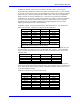
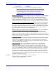
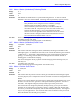
One common application type for which the default value of Ix02 cannot be used is the
direct pulse-and-direction output for stepper motor drives (PMAC2 only). This mode uses
the C output register alone for each channel, and I9n6 for Channel n must be set to 2 or 3
to get pulse frequency output.
In this case, the following values should be used:
Channel Address Channel Address
PWM1A $C002 PWM9A $C042
PWM2A $C00A PWM10A $C04A
PWM3A $C012 PWM11A $C052
PWM4A $C01A PWM12A $C05A
PWM5A $C022 PWM13A $C062
PWM6A $C02A PWM14A $C06A
PWM7A $C032 PWM15A $C072
PWM8A $C03A PWM16A $C07A
Channels 9 – 16 are on an ACC-24P/V2 board.