
Reference Manual


PMAC 2 Software Reference
428 PMAC I/0 and Memory Map
0 DISP0 Inversion Control
7 DISP7 Inversion Control
8 CTRL0 Inversion Control
11 CTRL3 Inversion Control (All bits: 0=Non-inverting;
1=Inverting) (All bits must be 0 to use standard port
accessories)
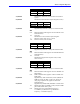
Y:$C088-$C08B
Not used
X:$C088-$C08B
Not used
Y:$C08C
Pure binary conversion from gray code input on I/O00
to I/O23
X:$C08C
Not used
Y:$C08D
Gray-to-binary conversion bit-length control
0-3 Bit length of less significant word portion (I/O00 -
I/Onn)
4 =1 specifies 16-bit lower / 8-bit upper conversion
5-23 Not used
X:$C08D
Not used
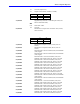
Y:$C08E
MACRO Node Enable Control (I996)
0 Node 0 enable control
15 Node 15 enable control (0=node disable; 1=node
enable)
16-19 Sync packet slave node number control
20-23 Master number control (Note: Bits 16-23 not present on
prototype PMAC2 boards with prototype
“DSPGATE2” ICs; production “DSPGATE2A” ICs
have full register)
X:$C08E
Not used
Y:$C08F
MACRO Ring Status and Control
0 Data overrun error (cleared when read)
1 Byte violation error (cleared when read)
2 Packet parity error (cleared when read)
3 Data underrun error (cleared when read)
4 Master station enable
5 Synchronizing master station enable
6 Sync packet received (cleared when read)
7 Sync packet phase lock enable
8 Node 8 master address check disable
9 Node 9 master address check disable
10 Node 10 master address check disable
11 Node 11 master address check disable
12 Node 12 master address check disable
13 Node 13 master address check disable
14 Node 14 master address check disable
15 Node 15 master address check disable
Note:
On prototype PMAC2 boards with prototype DSPGATE2 ICs, only bits 0, 1, 2 are
present; equivalent to bits 4, 1, and 2, respectively, of production boards with
DSPGATE2A ICs as listed above.