
Reference Manual


PMAC 2 Software Reference
380 PMAC Saved Setup Registers
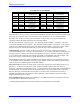
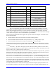
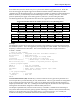
ACC-14P Port Entries
ACC 14 # Port Entry ACC 14 # Port Entry
1 A $35FFD0 4 A $35FFE8
1 B $35FFD3 4 B $35FFEB
1 C $36FFD0 4 C $36FFE8
1 D $36FFD3 4 D $36FFEB
2 A $35FFD8 5 A $35FFF0
2 B $35FFDB 5 B $35FFF3
2 C $36FFD8 5 C $36FFF0
2 D $36FFDB 5 D $36FFF3
3 A $35FFE0 6 A $35FFF8
3 B $35FFE3 6 B $35FFFB
3 C $36FFE0 6 C $36FFF8
3 D $36FFE3 6 D $36FFFB
Time-Base Entries ($4, $9, $A, $B): A time-base entry performs a scaled digital differentiation of the
value in the source register. It is most often used to perform “electronic cam” functions, slaving a motion
sequence to the frequency of a master encoder. There are two types of time-base entries: untriggered and
triggered. An untriggered time base does not provide a specific starting point in the master source data.
A triggered time base starts the differentiation upon receipt of a hardware trigger on the master encoder’s
channel, referenced to the position captured by that trigger. This can be used to create an absolute
synchronization between the master position and the slave trajectory.
Time-base entries are two-line entries. The first setup line contains the method digit and the address of
the source-data register. The second setup line contains the “time-base scale factor”. The first result line
contains the intermediate result value of the source data, saved for the next cycle to be able to compute
the differentiation. The second result line contains the final result, which is the differentiated value. Most
commonly this result is used as the time-base source for a coordinate system, so Ix93 for the coordinate
system points to this second line.
Untriggered Time Base ($4): In an untriggered time-base entry, the first setup line contains a “4” in the
method digit (bits 20 – 23) and the address of the source register in bits 0 – 15. The source register is
almost always the result register of an incremental encoder entry (e.g. 1/T) higher in the table (addresses
$0720 to $072D). For example, to use the result of the fourth line of the conversion table as a source, this
I-variable would be $400723.
The second setup line is the “time-base scale factor” which multiplies the differentiated source value.
The final result value equals 2 * Time-Base-Scale-Factor * (New Source Value - Old Source Value).
“New Source Value” and “Old Source Value” (stored from the previous servo cycle) are typically in units
of 1/32 of a count, the usual scaling of a 1/T encoder conversion result.
When this time base entry is used to calculate a frequency-based time base for a coordinate system, the
TBSF should be set to 2
17
/Real-Time Input Frequency (131,072/RTIF), where the Real-Time Input
Frequency (RTIF) in counts per millisecond, is the frequency at which motion trajectories using this time
base will execute at the programmed speed or in the programmed time. The motion sequence to be slaved
to this frequency should be written assuming that the master is always generating this real-time input
frequency (so always moving at the “real-time speed”). The true speed of trajectories using this time
base will vary proportionately with the actual input frequency.
Example
The application requires the use of Encoder 4 on board a PMAC2 as an untriggered time-base master for
Coordinate System 1. The real-time input frequency is selected as 256 counts/msec. The conversion
table starts with 8 single-line entries in Y:$0720 – Y:$0727, with the 4
th
line (Y:$0723) doing a 1/T
conversion of Encoder 4.