
Reference Manual


PMAC 2 Software Reference
PMAC Saved Setup Registers 373
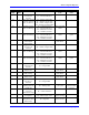
Turbo PMAC2 Ultralite Defaults
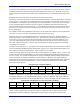
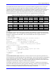
I-Var. Setting Meaning I-Var. Setting Meaning
Y:$0720 $28C0A0 MACRO Node 0 Reg. 0
Unshifted Read
Y:$0728 $28C0B0 MACRO Node 8 Reg. 0
Unshifted Read
Y:$0721 $FFFFFF Use all 24 bits Y:$0729 $FFFFFF Use all 24 bits
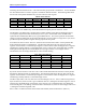
Y:$0722 $28C0A4 MACRO Node 1 Reg. 0
Unshifted Read
Y:$072A $28C0B4 MACRO Node 9 Reg. 0
Unshifted Read
Y:$0723 $FFFFFF Use all 24 bits Y:$072B $FFFFFF Use all 24 bits
Y:$0724 $28C0A8 MACRO Node 4 Reg. 0
Unshifted Read
Y:$072C $28C0B8 MACRO Node 12 Reg. 0
Unshifted Read
Y:$0725 $FFFFFF Use all 24 bits Y:$072D $FFFFFF Use all 24 bits
Y:$0726 $28C0AC MACRO Node 5 Reg. 0
Unshifted Read
Y:$072E $28C0BC MACRO Node 13 Reg. 0
Unshifted Read
Y:$0727 $FFFFFF Use all 24 bits Y:$072F $FFFFFF Use all 24 bits
Y:$0730 – Y:$073F = 0
Y:$0720 to Y:$073F form the 32 setup lines of the PMAC’s Encoder Conversion Table (ECT). The main
purpose of the ECT is to provide a pre-processing of feedback and master data to prepare it for use by the
servo loop. It can also be used to execute certain simple calculations at the servo update frequency.
Each setup line occupies a fixed register in the PMAC’s memory map. The register addresses are
important, because the results of the ECT are accessed by address.
The ECT has two halves: setup and results. The setup half resides in PMAC’s Y-memory, and can be
accessed through these 32 setup registers. The result half resides in PMAC’s X-memory. Each of the 32
setup lines has a matching result X-register at the same numerical address. If the entry consists of more
than one line, the last line has the final result; any previous lines contain intermediate results.
Table Structure: The ECT consists of a series of entries, with each entry creating one processed
(converted) feedback value. An entry in the ECT can have 1, 2, or 3 lines, with each line containing a 24-
bit setup word in Y-memory, and a 24-bit result register in X-memory. Therefore, each entry contains 1,
2, or 3 of these 24-bit setup lines, each usually represented as a hexadecimal value with six digits. The
final result is always in the X-memory register matching the last setup line in the entry.
The variables that commonly contain the address of the last line of the entry are Ix03 Motor x Position-
Loop Feedback Address, Ix04 Motor x Velocity-Loop Feedback Address, Ix05 Motor x Master Position
Address and Ix93 Coordinate System x Time-Base Address.
Entry First Line: The first line’s setup register in each entry consists of a source address in the low 16
bits (bits 0 – 15, the last four hex digits), which contains the PMAC address of the raw data to be
processed, a digit (the second hex digit, bits 16 - 19) that specifies how the source data is to be shifted and
whether the result is to be summed with the result of the above entry, and a method value in the high 4
bits (first hex digit), which specifies how this data is to be processed. If the first line in the entry is
$000000, this signifies the end of the active table, regardless of what subsequent entries in the table
(higher addressed registers) contain.
Entry Additional Lines: Depending on the method, 1 or 2 additional lines may be required in the entry
to provide further instructions on processing.
The following table summarizes the content of entries in the Encoder Conversion Table: