
User's Manual


PMAC VME Hardware Reference Manual
PMAC VME E-Point Descriptions 3
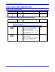
E8: RS232 Converter Power Supply Control
E Point and
Physical Layout
Location Description Default
E8
A4 Jump pin 1 to 2 to apply +5V to J4 pin 2 (JRS422);
this can be used to power optional RS422 to RS232
converter module which requires +5V for
operation.
Jumper installed
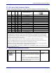
E9 - E16: Serial Interface Handshake Control
E9 to E16 jumpers control whether the RS-422 serial port will be in DCE or DTE format. The default
configuration permits straight-across connection to a PC DB-25 serial port.
E Point and
Physical Layout
Location Description Default
E9 E10
A3 Jump, E9-1 to E9-2 to allow RD- to be input on J4-
3; jump E10-1 to E10-2 to allow SD- to be output
on J4-5.
Jump E9-1 to E10-1 to allow RD- to be output on
J4-3; jump E9-2 to E10-2 to allow SD- to be input
on J4-5.
1-2 Jumper
installed
E11 E12
A3 Jump E11-1 to E11-2 to allow RD+ to be input on
J4-4; jump E12-1 to E12-2 to allow SD+ to be
output on J4-6.
Jump E11-1 to E12-1 to allow RD+ to be output on
J4-4; jump E11-2 to E12-2 to allow SD+ to be
input on J4-6.
1-2 Jumper
installed
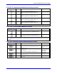
E13 E14
A4 D5 jump E13-1 to E13-2 to 1-2 allow CS+ to be
input jumper on J4-7; jump E14-1 to installed E14-
2 to allow RS+ to be output on J4-9.
Jump E13-1 to E14-1 to allow CS+ to be output on
J4-7; jump E13-2 to E14-2 to allow RS+ to be input
on J4-9.
1-2 Jumper
installed
E15 E16
A4 D5 jump E15-1 to E15-2 to allow CS- to be input
on J4-8.
Jump E16-1 to E16-2 to allow RS- to be output on
J4-10.
Jump E15-1 to E16-1 to allow CS- to be output on
J4-8; jump E15-2 to E16-2 to allow RS- to be input
on J4-10.
1-2 Jumper
installed