
User's Manual


PMAC VME Hardware Reference Manual
2 PMAC VME E-Point Descriptions
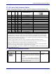
E3 - E6: Servo Clock Frequency Control
The servo clock (which determines how often the servo loop is closed) is derived from the phase clock
(see E29 - E33) through a "divide-by-N" counter. Jumpers E3 through E6 control this dividing function.
E3 E4 E5 E6 Servo Clock = Phase
Clock Divided by N
Default and Physical Layout
E3 E4 E5 E6
Location: B4 B4 B5 B5
ON ON ON ON N = divided by 1
OFF ON ON ON N = divided by 2
ON OFF ON ON N = divided by 3
OFF OFF ON ON N = divided by 4 Only E5 and E6 ON
ON OFF ON ON N = divided by 5
OFF ON OFF ON N = divided by 6 Only E4 and E6 ON (option 5 only)
ON OFF OFF ON N = divided by 7
OFF OFF OFF ON N = divided by 8
ON ON ON OFF N = divided by 9
OFF ON ON OFF N = divided by 10
ON OFF ON OFF N = divided by 11
OFF OFF ON OFF N = divided by 12
ON ON OFF OFF N = divided by 13
OFF ON OFF OFF N = divided by 14
ON OFF OFF OFF N = divided by 15
OFF OFF OFF OFF N = divided by 16
The setting of I-variable I10 should be adjusted to match the servo interrupt cycle time set by E98, E3 -- E6,
E29 -- E33, and the crystal clock frequency. I10 holds the length of a servo interrupt cycle, scaled so that
8,388,608 equals one millisecond. Since I10 has a maximum value of 8,388,607, the servo interrupt cycle
time should always be less than a millisecond (unless you want to make your basic unit of time on PMAC
something other than a millisecond). To have a servo sample time greater than one millisecond, the sampling
may be slowed in software with variable Ix60.
Frequency can be checked on J4 pins 21 and 22. It can also be checked from software by typing
RX:0 in the PMAC terminal at 10-second intervals and dividing the difference of successive responses by
10000. The resulting number is the approximate servo clock frequency in kHz.
If E40-E43 are set up so that the card has a software address other than @0, the servo clock signal must be
received over the serial port from card @0, so these jumpers have no effect.
All versions of the PMAC except Option 5 (30MHz), have a 19.6608MHz ("20MHz) clock crystal, even the
40 and 60 MHz CPU versions.
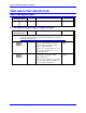
E7: Machine Input Source/Sink Control
E Point and
Physical Layout
Location Description Default
E7
A4 Jump pin 1 to 2 to apply +5V to input reference
resistor sip pack; this will bias MI1 to MI8 inputs
to +5V for off state; input must then be grounded
for on state.
Jump pin 2 to 3 to apply GND to input reference
resistor sip pack; this will bias MI1 to MI8 inputs
to GND for off state; input must then be pulled up
for on state (+5V to +24V).
1-2 Jumper
installed