
User's Manual


PMAC VME Hardware Reference Manual
PMAC VME E-Point Descriptions 13
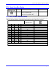
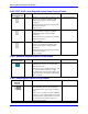
E185, E187, E188: Host-Supplied Analog Power Source Enable
E Point and
Physical Layout
Location Description Default
E185
B2 Jump pin 1 to pin 2 to allow A+14V to come
from P1 (ties amplifier and PMAC VME
power supply together. Defeats OPTO
coupling.)
Note that if E185 is changed, E188 and E187
must also be changed.
Also see E190.
No jumper installed
E187
A1 Jump pin 1 to pin 2 to allow analog GND to
come from P1 (ties amplifier and PMAC
VME GND together. Defeats OPTO
coupling.)
Note that if E187 is changed, E185 and E188
must also be changed.
Also, see E190.
No jumper
E188
A2 Jump pin 1 to pin 2 to allow A-14V to come
from P1 (ties amplifier and PMAC VME
power supply together. Defeats OPTO
coupling.)
Note that if E188 is changed; E187 and E185
must also be changed.
Also, see E190.
No jumper
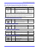
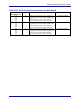
E189: Amplifier-Supplied Switch Pull-Up Enable
E Point and
Physical Layout
Location Description Default
E189
A2 Jump pin 1 to 2 to allow A+15V/+V on P2A
(JMACH2) pin 59, to tie to A+15V on P2
(JMACH1) pin C30.
This jumper must be installed to allow A+15V
to power the OPTO switch sensor inputs
(including limits) from the same OPTO-power
supply that powers the amplifier output stage.
Also, see E190
1-2 Jumper installed
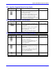
E190: Host-Supplied Switch Pull-Up Enable
E Point and
Physical
Layout
Location Description Default
E190
D1 Jump pin 1 to 2 to allow A+15V/OPT+V on
P2A (JMACH2) pin C30, (also see E189) to
power OPTO switch sensor inputs (including
limits).
Jump pin 2 to 3 to allow +12V from VME bus
connector to power OPTO switch sensor inputs
(including limits). Optical isolation is then lost.
See also E185, E187, E188, and figure on
PMAC OPTO isolation
1-2 Jumper installed