
User's Manual


PMAC VME Hardware Reference Manual
10 PMAC VME E-Point Descriptions
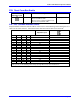
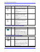
E89: Amplifier-Supplied Switch Pull-Up Enable
E Point and
Physical Layout
Location Description Default
E89
A2 Jump pin 1 to 2 to supply flags from A+15V
input (P2 pin C30). E90 must jump pins 1 to
2 to bring power to flags.
Jump pin 2 to 3 to supply flags from A+V
input on option 1V (P2 pin C30). E90 must
jump pins 1 to 2 to bring power to flags.
See also E85, E87, E88, E89 and PMAC VME
power supply connection diagram.
1-2 Jumper installed
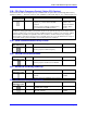
E90: Host-Supplied Switch Pull-Up Enable
E Point and
Physical Layout
Location Description Default
E90
D1 Jump pin 1 to 2 to allow A+15V/OPT+V on
P2 or P2A (JMACH) pin C30, (also see E89)
to supply flags.
Jump pin 2 to 3 to allow +12V from VME
bus connector to supply flags. Optical
isolation is then lost.
See also E85, E87, E88, E89 and PMAC
VME power supply connection diagram.
1-2 Jumper installed
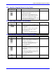
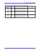
E93 - E94: Compare-Equal Output Voltage Configure
E Point and
Physical Layout
Location Description Default
E93
A3 Jump pin 1 to 2 to apply +V (+5V to +24V)
to pin 11 of U28 (should be ULN2803A for
sink output configuration).
Jump pin 2 to 3 to apply GND to pin 11 of
U28 (should be UDN2981A for source
output configuration).
Also, see E2
1-2 Jumper installed
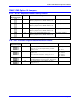
E94
B3 Jump pin 1 to 2 to apply GND to pin 10 of
U28 (Should be ULN2803A for sink output
configuration).
Jump pin 2 to 3 to apply +V (+5V to +24V)
to pin 10 of U28 (Should be UDN2981A for
source output configuration).
Also, see E1
1-2 Jumper installed
E95
A3 Reserved for future use. No jumper