
User's Manual


PMAC VME Hardware Reference Manual
PMAC VME E-Point Descriptions 9
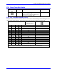
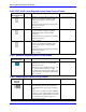
E72 - E73: Panel Analog Time Base Signal Enable
E Point and
Physical Layout
Location Description Default
E72
C3 Jump pin 1 to 2 to allow V to F converter
FOUT derived from wiper input on J2 to
connect to CHA4.
No jumper
installed
E73
C3 Jump pin 1 to 2 to allow V to F converter
FOUT/ derived from wiper input on J2 to
connect to CHA4/.
No jumper
installed
With these jumpers ON, no encoder should be wired into ENC4 on JMACH1. E27 must connect pins 1 to
2 because these are single-ended inputs. Variable I915 should be set to 4 to create a positive voltage
(frequency) number in PMAC.
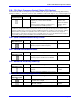
E74 - E75: Clock Output Control for External Interpolation
E Point and
Physical Layout
Location Description Default
E74
C3 Jump pin 1 to 2 to allow SCLK/ to output on
CHC4/.
No jumper
installed
E75
C3 Jump pin 1 to 2 to allow SCLK to output on
CHC4.
No jumper
installed
SCLK out permits synchronous latching of analog encoder interpolators such as Acc-8D Opt 8.
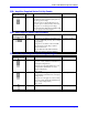
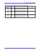
E85, E87, E88: Host-Supplied Analog Power Source Enable
E Point and
Physical Layout
Location Description Default
E85
B2 Jump pin 1 to pin 2 to allow A+14V to come
from P1 (ties amplifier and PMAC VME
power supply together. Defeats OPTO
coupling.)
Note that if E85 is changed, E88 and E87 must
also be changed.
Also, see E90.
No jumper
E87
D1 Jump pin 1 to pin 2 to allow analog GND to
come from P1 (ties amplifier and PMAC VME
GND together. Defeats OPTO coupling.)
Note that if E87 is changed, E85 and E88 must
also be changed.
Also, see E90.
No jumper
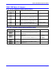
E88
A2 Jump pin 1 to pin 2 to allow A-14V to come
from P1 (ties amplifier and PMAC VME
power supply together. Defeats OPTO
coupling.)
Note that if E88 is changed; E87 and E85 must
also be changed.
Also, see E90.
No jumper