
Reference Manual


PMAC-PC Hardware Reference
PMAC-PCI Base Board Connector Pinouts 53
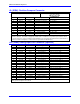
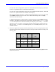
JS2: A/D Port 2 Connector
JS2 (16-Pin Header)
Front View
Pin # Symbol Function Description Notes
1 DCLK Output D to A, A to D Clock DAC and ADC clock for Chan. 5,
6, 7, 8
2 BDATA2 Output D to A Data DAC data for Chan. 5, 6, 7, 8
3 ASEL2/ Output Chan. Select Bit 2 DAC data for Chan. 5, 6, 7, 8
4 ASEL3/ Output Chan. Select Bit 3 Select for Chan. 5, 6, 7, 8
5 CNVRT23 Output A to D Convert ADC convert sig. Chan 5, 6, 7, 8
6 ADCIN2 Input A to D Data ADC data for Chan. 5, 6, 7, 8
7 OUT5/ Output Amp-Enable/Dir. Amp Enable/Dir for Chan. 5
8 OUT6/ Output Amp-Enable/Dir. Amp Enable/Dir for Chan 6
9 OUT7/ Output Amp-Enable/Dir. Amp Enable/Dir for Chan 7
10 OUT8/ Output Amp-Enable/Dir. Amp Enable/Dir for Chan 8
11 HF45 Input Amp. Fault Amp Enable/Dir for Chan 5
12 HF46 Input Amp. Fault Amp Enable/Dir for Chan 6
13 HF47 Input Amp. Fault Amp Enable/Dir for Chan 7
14 HF48 Input Amp. Fault Amp Enable/Dir for Chan 8
15 +5V Output +5V Supply Power supply out
16 GND Common PMAC Common
Acc-28A/B connection; digital amplifier connection.
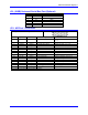
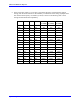
TB1 (JPWR)
Top View
Pin # Symbol Function Description Notes
1 GND Common Digital Ground
2 +5V Input +5V Supply Ref. to digital GND.
3 +12V Input +12V to15V Supply Ref. to digital GND.
4 -12V Input -12V to15V Supply Ref. to digital GND.
This terminal block may be used as an alternative power supply connector if PMAC PCI is not installed in a PC-
bus. The +5V powers the digital electronics. The +12V and -12V, if jumpers E85, E87, and E88 are installed,
power the analog output stage (this defeats the optical isolation on PMAC).
To keep the optical isolation between the digital and analog circuits on PMAC, provide analog power (+/-12V to
+/-15V and AGND) through the JMACH connector, instead of the bus connector or this terminal block.