
Reference Manual


PMAC-PC Hardware Reference
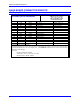
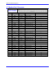
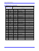
48 PMAC-PCI Base Board Connector Pinouts
J7 JMACH2
(60-Pin Header)
Continued
Front View
Pin # Symbol Function Description Notes
40 -LIM8 Input Positive End Limit 8 8,9
41 HMFL7 Input Home-Flag 7 10
42 HMFL8 Input Home-Flag 8 10
43 DAC5 Output Analog Out Pos. 5 4
44 DAC6 Output Analog Out Pos. 6 4
45 DAC5/ Output Analog Out Neg. 5 4,5
46 DAC6/ Output Analog Out Neg. 6 4,5
47 AENA5/DIR5 Output Amp-Enable/Dir. 5 6
48 AENA6/DIR6 Output Amp-Enable/Dir. 6 6
49 FAULT5 Input Amp-Fault 5 7
50 FAULT6 Input Amp-Fault 6 7
51 +LIM5 Input Negative End Limit 5 8,9
52 +LIM6 Input Negative End Limit 6 8,9
53 -LIM5 Input Positive End Limit 5 8,9
54 -LIM6 Input Positive End Limit 6 8,9
55 HMFL5 Input Home-Flag 5 10
56 HMFL6 Input Home-Flag 6 10
57 ORST/ Output Reset Signal Indicator/driver
58 AGND Input Analog Common
59 A+15V/OPT+V Input Analog +15V/Flag Supply
60 A-15V Input Analog -15V Supply
The J7 connector is used to connect the PMAC to the second 4 channels (Channels 5, 6, 7, and 8) of servo
amps, flags, and encoders.
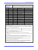
Note 1: In standalone applications, these lines can be used as +5V power supply inputs to power PMAC's
digital circuitry. However, if a terminal block is available on your version of PMAC, it is preferable to
bring the +5V power in through the terminal block.
Note 2: Referenced to digital common (GND). Maximum of +
12V permitted between this signal and its
complement.
Note 3: Leave this input floating if not used (i.e. digital single-ended encoders). In this case, jumper (E18
- 21, E24 - 27) for channel should hold input at 2.5V.
Note 4: +
10V, 10mA max, referenced to analog common (AGND).
Note 5: Leave floating if not used; do not tie to AGND. In this case, AGND is the return line.
Note 6: Functional polarity controlled by jumper(s) E17. Choice between AENA and DIR use controlled
by Ix02 and Ix25.
Note 7: Functional polarity controlled by variable Ix25. Must be conducting to 0V (usually AGND) to
produce a '0' in PMAC software. Automatic fault function can be disabled with Ix25.
Note 8: Pins marked -LIMn should be connected to switches at the positive end of travel. Pins marked
+LIMn should be connected to switches at the negative end of travel.
Note 9: Must be conducting to 0V (usually AGND) for PMAC to consider itself not into this limit.
Automatic limit function can be disabled with Ix25.
Note 10: Functional polarity for homing or other trigger use of HMFLn controlled by Encoder/Flag
Variable 2 (I902, I907, etc.) HMFLn selected for trigger by Encoder/Flag Variable 3 (I903, I908, etc.).
Must be conducting to 0V (usually AGND) to produce a 0 in PMAC software.