
Reference Manual


PMAC-PC Hardware Reference
44 PMAC-PCI Base Board Connector Pinouts
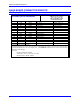
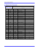
J4: Serial Port Connector
J4 JRS422 (26-Pin Connector)
Front View
Pin # Symbol Function Description Notes
1 CHASSI Common PMAC Common
2 S+5V Output +5VDC Supply Deactivated by E8
3 RD- Input Receive Data Diff. I/O low TRUE **
4 RD+ Input Receive Data Diff. I/O high TRUE *
5 SD- Output Send Data Diff. I/O low TRUE **
6 SD+ Output Send Data Diff. I/O high TRUE *
7 CS+ Input Clear to Send Diff . I/O high TRUE **
8 CS- Input Clear to Send Diff. I/O low TRUE *
9 RS+ Output Req. to Send Diff. I/O high TRUE **
10 RS- Output Req. to Send Diff. I/O low TRUE *
11 DTR Bidirectional Data Terminal Ready Tied to DSR
12 INIT/ Input PMAC Reset Low is RESET
13 GND Common PMAC Common Low is RESET
14 DSR Bidirectional Data Set Ready Tied to DTR
15 SDIO- Bidirectional Special Data Diff. I/O low TRUE
16 SDIO+ Bidirectional Special Data Diff. I/O high TRUE
17 SCIO- Bidirectional Special CTRL. Diff I/O low TRUE
18 SCIO+ Bidirectional Special CTRL. Diff. I/O high TRUE
19 SCK- Bidirectional Special Clock Diff. I/O low TRUE
20 SCK+ Bidirectional Special Clock Diff. I/O high TRUE
21 SERVO- Bidirectional Servo Clock Diff. I/O low TRUE
22 SERVO+ Bidirectional Servo Clock Diff. I/O high TRUE ***
23 PHASE- Bidirectional Phase Clock Diff I/O low TRUE ***
24 PHASE+ Bidirectional Phase Clock Diff. I/O high TRUE ***
25 GND Common PMAC Common
26 +5V Output +5VDC Supply Power supply out
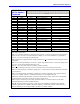
The JRS422 connector provides the PMAC with the ability to communicate both in RS422 and RS232. In
addition, this connector is used to daisy chain interconnect multiple PMACs for synchronized operation.
Jumper E110 selects between RS-232 or RS-422 signal types.
Jumper E110 enables or disables the use of the PHASE, SERVO and INIT lines
* Note: Required for communications to an RS-422 host port
** Note: Required for communications to an RS-422 or RS-232 host port
*** Note: Output on card @0; input on other cards. These pins are for synchronizing multiple PMACs
together by sharing their phasing and servo clocks. The PMAC designated as card 0 (@0) by its jumpers
E40-E43 outputs its clock signals. Other PMACs designated as cards 1-15 (@1-@F) by their jumpers
E40-E43 take these signals as inputs. If synchronization is desired, these lines should be connected even
if serial communications is not used.
See Also:
Serial Communications
Synchronizing PMAC to other PMACs