
Reference Manual


PMAC-PCI Hardware Reference
Machine Connection 35
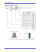
Thumbwheel Multiplexer Port (JTHW Port)
The Thumbwheel Multiplexer Port, or Multiplexer Port, on the JTHW (J3) connector has eight input lines
and eight output lines. The output lines can be used to multiplex large numbers of inputs and outputs on
the port, and Delta Tau provides accessory boards and software structures (special M-variable definitions)
to capitalize on this feature. Up to 32 of the multiplexed I/O boards may be daisy-chained on the port, in
any combination.
The Acc-18 Thumbwheel Multiplexer board provides up to 16 BCD thumbwheel digits or 64 discrete
TTL inputs per board. The TWD and TWB forms of M-variables are used for this board. The Acc-34x
family Serial I/O Multiplexer boards provide 64 I/O point per board, optically isolated from PMAC. The
TWS form of M-variables is used for these boards. The Acc-8D Option 7 Resolver-to-Digital Converter
board provides up to four resolver channels whose absolute positions can be read through the thumbwheel
port. The TWR form of M-variables is used for this board. The Acc-8D Option 9 Yaskawa
TM
Absolute
Encoder Interface board can connect to up to four of these encoders. The absolute position is read serially
through the multiplexer port on power up.
If none of these accessory boards is used, the inputs and outputs on this port may be used as discrete, non-
multiplexed I/O. They map into PMAC’s processor space at Y address $FFC1. The suggested M-
variable definitions for this use are M40 to M47 for the eight outputs, and M50 to M57 for the eight
inputs. The Acc-27 Optically Isolated I/O board buffers the I/O in this non-multiplexed form, with each
point rated to 24V and 100 mA.
Optional Analog Inputs (JANA Port)
The JANA port is present only if Option 12 is ordered for the PMAC PCI. Option 12 provides eight 12-
bit analog inputs (ANAI00-ANAI07). Option 12A provides eight additional 12-bit analog inputs
(ANA08-ANAI15) for a total of 16 inputs. The analog inputs can be used as unipolar inputs in the 0V to
+5V range, or bi-polar inputs in the -2.5V to +2.5V range.
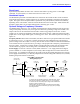
The analog-to-digital converters on PMAC require +5V and -12V supplies. These supplies are not
isolated from digital +5V circuitry on PMAC. If the PMAC is plugged into the PCI bus, these supplies
are taken from the bus power supply. In a standalone application, these supplies must be brought in on
terminal block TB1. The -12V and matching +12V supply voltages are available on the J30 connector to
supply the analog circuitry providing the signals.
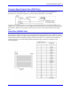
Only one pair of analog-to-digital converter registers is available to the PMAC processor at any given
time. The data appears to the processor at address Y:$FFC8. The data from the selected analog input 0 to
7 (ANAI00-ANAI07) appears in the low 12 bits; the data from the selected analog input 8 to 15
(ANAI08-ANAI15) appears in the high 12 bits (this data is only present if Option 12A has been ordered).
The input is selected and the conversion is started by writing to this same word address Y:$FFC8. A
value of 0 to 7 written into the low 12 bits selects the analog input channel of that number (ANAI00-
ANAI07) to be converted in unipolar mode (0V to +5V). A value of 0 to 7 written into the high 12 bits
selects the analog input channel numbered 8 greater (ANAI08-ANAI15) in unipolar mode. If the value
written into either the low 12 bits or the high 12 bits is 8 higher (8 to 15), the same input channel is
selected, but the conversion is in bipolar mode (-2.5V to +2.5V).
PMAC variables I60 and I61 allows an automatic conversion of the analog inputs. Setting I60=$FFC8
and I61 with the number of converted registers desired minus 1, the converted data can be found in
registers $0708 to $070F. See the PMAC Software Reference for further details on this.