
Reference Manual


PMAC-PCI Hardware Reference
34 Machine Connection
Reset Input
Input INIT/ (reset) affects the entire card. It has the same effect as cycling power or a host $$$
command. It is hard-wired, so it retains its function even if I2 is set to 1.
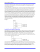
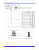
Handwheel Inputs
The handwheel inputs HWCA and HWCB can be connected to the second encoder counter on PMAC
with jumpers E22 and E23. If these jumpers are on, nothing else should be connected to the Encoder 2
inputs. The signal can be interpreted either as quadrature or as pulse (HWCA) and direction (HWCB),
depending on the value of I905. I905 also controls the direction sense of this input. Make sure that the
Encoder 2 jumper E26 is set for single ended signals, connecting pins 1 and 2.
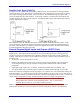
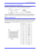
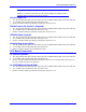
Optional Voltage to Frequency Converter
The WIPER analog input (0 to +10V on PMAC PCI referenced to digital ground) provides an input to a
voltage-to-frequency converter (V/F) with a gain of 25 kHz/Volt, providing a range of 0-250 kHz. The
output of the V/F can be connected to the Encoder 4 counter using jumpers E72 and E73. If these
jumpers are on, nothing else should be connected to the Encoder 4 inputs. Make sure that the Encoder 4
jumper E24 is set for single-ended signals, connecting pins 1 and 2. This feature requires the ordering of
Option-15.
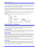
Frequency Decode: When used in this fashion, Encoder 4 must be set up for pulse-and-direction decode
by setting I915 to 0 or 4. A value of 4 is usually used, because with CHB4 (direction) unconnected, a
positive voltage causes the counter to count up. The encoder conversion table can then take the difference
in the counter each servo cycle and scale it, providing a value proportional to frequency, and therefore to
the input voltage. Usually this is used for feedrate override (time base control), but the resulting value
can be used for any purpose. The resulting value in the default setup can be found at X:$729,24
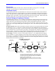
Power Supply: For the V/F converter to work, PMAC must have +/-12V supply referenced to digital
ground. If PMAC is in a bus configuration, this usually comes through the bus connector from the bus
power supply. In a standalone configuration, this supply must still be brought through the bus connector
(or the supply terminal block), or it must be jumpered over from the analog side with E85, E87, and E88,
defeating the optical isolation on the board.
(Optional user
provided +10V)
Hardware Voltage-to-
Frequency Converter
Software-Configured
Hardware Counter
Software
Interpolation
Pulse Train
0 to 250 KHz
Integer
Count
+5V
J2
25
20
26
-5Kohm
Wiper
GND
Voltage
0 to +10V
V/F
25 KHz/V
E73
(E24:1-2)
I915=4
E72
CHA4
CHA4/
24
X:$C00C+
Y:$723=$00C00C
X:$723
24
24
Interpolated
Count
Value
Proportional
to Voltage
ENC4
Decoder/
Counter
1/T
Encoder
Conversion
“Time
Base”
Conversion
Software
Differentiation
X:$729
Y:$728=$400723
Y:$729=Scaling
To use this value for feedrate override for a coordinate system, set the
time base source address I-Variable (Ix93 for C.S.x.) to 1833 ($729).
To use this value for some other purpose, assign an M-Variable to this
register (e.g., M60->X:$729,0-24-,U).
Scaling is set by the value in Y:$729 (for the default conversion table).
This value can be determined interactively by varying the input voltage
and noting the effect.
Using PMAC’s Control Panel
Analog (Wiper) Input