
Reference Manual


PMAC-PCI Hardware Reference
30 Machine Connection
If Pin 1 of the resistor pack, marked by a dot on the pack, matches Pin 1 of the socket, marked by a wide
white line on the front side of the board, and a square solder pin on the back side of the board, then the
pack is configured as a bank of pull-down resistors. If the pack is reversed in the socket, it is configured
as a bank of pull-up resistors.
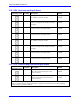
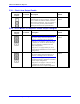
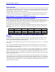
The following table lists the pull-up/pull-down resistor pack for each input device:
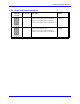
Device Resistor Pack Pack Size Device Resistor Pack Pack Size
Encoder 1 RP60 6-pin Encoder 5 RP97 6-pin
Encoder 2 RP62 6-pin Encoder 6 RP99 6-pin
Encoder 3 RP66 6-pin Encoder 7 RP103 6-pin
Encoder 4 RP68 6-pin Encoder 8 RP105 6-pin
Incremental Encoder Connection
Each JMACH connector provides two +5V outputs and two logic grounds for powering encoders and
other devices. The +5V outputs are on pins 1 and 2; the grounds are on pins 3 and 4. The encoder signal
pins are grouped by number: all those numbered 1 (CHA1, CHA1/, CHB1, CHC1, etc.) belong to encoder
#1. The encoder number does not have to match the motor number, but usually does. If the PMAC is not
plugged into a bus and drawing its +5V and GND from the bus, use these pins to bring in +5V and GND
from the power supply. Connect the A and B (quadrature) encoder channels to the appropriate terminal
block pins. For encoder 1, the CHA1 is pin 25, CHB1 is pin 21. If using a single-ended signal, leave the
complementary signal pins floating – do not ground them. However, if single-ended encoders are used,
please check the settings of the jumpers E18 to E21 and E24 to E27. For a differential encoder, connect
the complementary signal lines – CHA1/ is pin 27, and CHB1/ is pin 23. The third channel (index pulse)
is optional; for encoder 1, CHC1 is pin 17, and CHC1/ is pin 19.
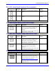
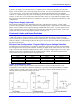
Example: differential quadrature encoder connected to channel #1:
DAC Output Signals
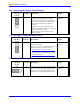
If PMAC is not performing the commutation for the motor, only one analog output channel is required to
command the motor. This output channel can be either single-ended or differential, depending on what
the amplifier is expecting. For a single-ended command using PMAC channel 1, connect DAC1 (pin 43)
to the command input on the amplifier. Connect the amplifier’s command signal return line to PMAC's
AGND line (pin 58). In this setup, leave the DAC1/ pin floating; do not ground it.
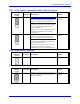
For a differential command using PMAC Channel 1, connect DAC1 (pin 43) to the plus command input
on the amplifier. Connect DAC1/ (pin 45) to the minus-command input on the amplifier. PMAC’s
AGND should still be connected to the amplifier common. If the amplifier is expecting separate sign and
magnitude signals, connect DAC1 (pin 43) to the magnitude input. Connect AENA1/DIR1 (pin 47) to the
sign (direction input). Amplifier signal returns should be connected to AGND (pin 58). This format
requires some parameter changes on PMAC; (see Ix25. Jumper E17 controls the polarity of the direction
output; this may have to be changed during the polarity test.