
Reference Manual


PMAC-PCI Hardware Reference
Machine Connection 29
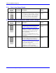
Home Switches
While normally closed-to-ground switches are required for the overtravel limits inputs, the home switches
could be either normally close or normally open types. The polarity is determined by the home sequence
setup, through the I-variables I902, I907, ... I977. However, for the following reasons, the same type of
switches used for overtravel limits are recommended:
Normally closed switches are proven to have greater electrical noise rejection than normally open types.
Using the same type of switches for every input flag simplifies maintenance stock and replacements.
Motor Signals Connections (JMACH Connectors)
Resistor Pack Configuration: Termination Resistors
The PMAC PCI provides sockets for termination resistors on differential input pairs coming into the
board. As shipped, there are no resistor packs in these sockets. If these signals are brought long distances
into the PMAC PCI board and ringing at signal transitions is a problem, SIP resistor packs may be
mounted in these sockets to reduce or eliminate the ringing.
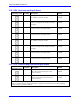
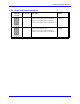
All termination resistor packs are the type that has independent resistors (no common connection) with
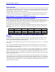
each resistor using 2 adjacent pins. The following table shows which packs are used to terminate each
input device:
Device Resistor Pack Pack Size Device Resistor Pack Pack Size
Encoder 1 RP61 6-pin Encoder 5 RP98 6-pin
Encoder 2 RP63 6-pin Encoder 6 RP100 6-pin
Encoder 3 RP67 6-pin Encoder 7 RP104 6-pin
Encoder 4 RP69 6-pin Encoder 8 RP106 6-pin
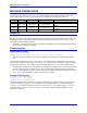
Resistor Pack Configuration: Differential or Single-Ended Encoder
Selection
The differential input signal pairs to the PMAC PCI have user-configurable pull-up/pull-down resistor
networks to permit the acceptance of either single-ended or differential signals in one setting, or the
detection of lost differential signals in another setting.
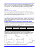
The ‘+’ inputs of each differential pair each have a hard-wired 1 kΩ pull-up resistor to +5V. This cannot
be changed.
The ‘-‘ inputs of each differential pair each have a hard-wired 2.2 kΩ resistor to +5V; each also has
another 2.2 kΩ resistor as part of a socketed resistor pack that can be configured as a pull-up resistor to
+5V, or a pull-down resistor to GND.
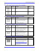
If this socketed resistor is configured as a pull-down resistor (the default configuration), the combination
of pull-up and pull-down resistors on this line acts as a voltage divider, holding the line at +2.5V in the
absence of an external signal. This configuration is required for single-ended inputs using the ‘+’ lines
alone; it is desirable for unconnected inputs to prevent the pick-up of spurious noise; it is permissible for
differential line-driver inputs.
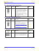
If this socketed resistor is configured as a pull-up resistor (by reversing the SIP pack in the socket), the
two parallel 2.2 kΩ resistors act as a single 1.1 kΩ pull-up resistor, holding the line at +5V in the absence
of an external signal. This configuration is required if encoder-loss detection is desired; it is required if
complementary open-collector drivers are used; it is permissible for differential line-driver inputs even
without encoder loss detection.